Nowadays, the cam and follower mechanism is used in different applications, you may have seen this mechanism in applications like IC engines, clocks, industrial equipment, toys, etc. Thus in this article, we are discussing the cam and follower mechanism in detail.
Contents:
What is Cam and Follower mechanism?
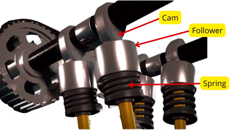
The cam and follower are the machine elements that help to convert rotational or translational motion into reciprocating or oscillating motion. The cam is the driver element while the follower is the driven element.
The cam is the rotating/translatory element that rotates/translates at a constant speed while the follower continuously makes contact with the cam profile and follows the motion predetermined by the cam profile.
The below figure shows the cam and follower mechanism.
The motion of the follower is predetermined by the cam profile. This feature of this mechanism helps to obtain different motions of the follower by properly designing the cam profile.
At higher speeds, the cam and follower mechanism provides highly accurate motion with zero or fewer degrees of error. Thus it is used in a variety of applications that requires precise movement of components at high speeds.
Example:- Operating of valves of IC engine.
The follower makes line contact with the cam profile. thus this mechanism forms a higher kinematic pair.
Terminology of cam and follower:
Following are the important terms used in the cam and follower:-
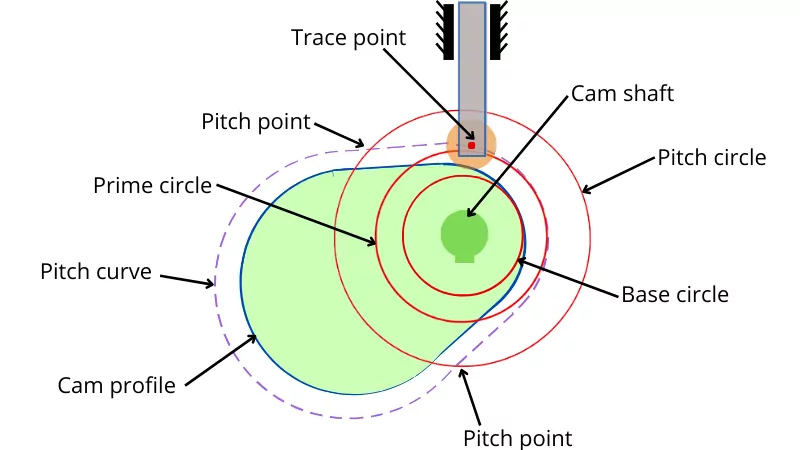
1] Base circle:- It is the smallest circle drawn about the center of rotation of the cam which should be tangent to the cam profile.
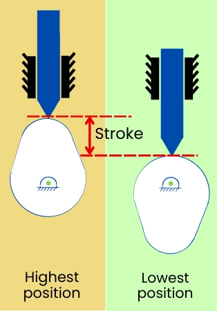
2] Lift/Stroke:- It is the distance/angle traveled by a follower from its lowest position to the highest position.
In the case of cam and follower, the stroke is classified as out/rise stroke and return/descent stroke.
When the follower moves from its lowest position to the highest position then this stroke is known as out stroke.
When the follower moves from its highest position to the lowest position then this stroke is known as the return stroke.
3] Trace point:- It is the point on the follower that helps to make a pitch curve around the cam profile. For the knife-edge follower, the trace point is the contact point between the follower and the cam and for the roller follower, the trace point is the center of the roller.
4] Pitch curve:- It is the curve generated by the trace point of the follower around the cam profile. For knife-edge follower, the cam profile is the same as the pitch curve.
5] Pressure angle:- At the contact point between the cam and follower, the normal drawn to the cam profile makes an angle with the direction of the follower. This angle is known as a pressure angle. The pressure angle is different for the different points on the cam profile.
6] Pitch point:- It is the point on the pitch curve where the value of pressure angle is maximum.
7] Pitch circle:- The circle drawn from the center of the cam that passes through the pitch points is known as the pitch circle.
8] Angle of rise/Ascent or out stroke angle (`\theta_{o}`):- It is the angle turned by the cam during the upward movement of the follower.
9] Angle of descent/Return (`\theta_{R}`):- It is the angle turned by the cam during the downward movement of the follower.
10] Dwell angle:- It is the angle turned by the cam when the follower remains stationary.
11] Angle of action: It is the angle turned by the cam from the starting of rise/out stroke to the end of the return stroke.
Types of cam:
Based on the different criteria the cams are classified as follows:-
A] According to shape of cam:-
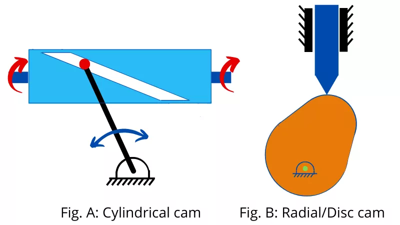
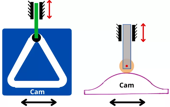
1] Cylindrical cam:- In the case of a cylindrical cam, the follower moves in the direction parallel to the axis of rotation of the cam. As shown in below Fig-A, the cylindrical cam has a groove on its surface for guiding the follower.
2] Radial or disc cam:- In the case of radial cam, the follower reciprocates or oscillates in a direction perpendicular to the axis of the cam. The below Fig-B shows the radial or disc cam.
B] According to motion of follower:-
According to the nature of motion, the cams are classified as follows:-
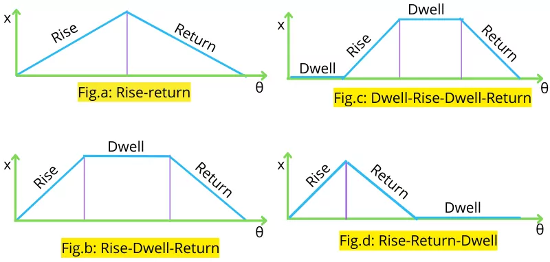
1] Rise-return:- In this case, the cam profile is designed in such a way that, the follower only performs rise and return strokes without having any dwell period. Below Fig-a shows a displacement diagram for the Rise-Return type of cam.
2] Rise-Dwell-Return:- In this case, a dwell is provided after the follower rise to the upper position, and after that, the follower returns to the lower position. Below Fig-b shows the displacement diagram for the Rise-Dwell-Return type of cam.
3] Dwell-Rise-Dwell-Return:- In this case, a dwell period is provided before the follower starts to rise and before the follower starts to return. The below Fig-c indicates the displacement diagram of this type of cam.
4] Rise-Return-Dwell:- In this type of cam, a dwell period is provided after completion of the rise and return stroke. Below Fig-d shows the displacement diagram for the rise-return-dwell type of cam.
C] According to motion of cam:-
Depending on motion, the cam is classified as follows:-
1] Rotating cam:- This type of cam rotates at a constant speed.
2] Translating cam:- The translating cam is a grooved or contoured plate that reciprocates to actuate the follower. The below figure shows the translating cam.
Types of follower:
The follower is classified on the basis of different criteria as follows:-
1] According to the shape of follower:-
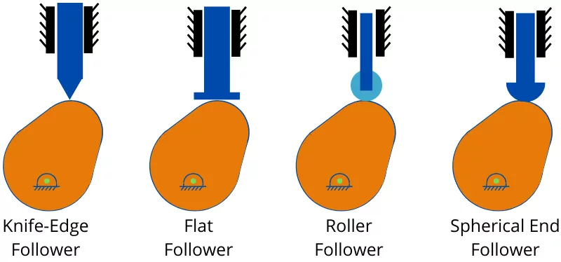
a] Knife edge follower:- The knife-edge follower has a sharp edge that touches the cam profile. This type of follower has higher wear at the tip and it can damage the cam profile earlier.
b] Flat follower:- This type of follower has a flat surface at the contact point. The flat follower has wear and tear less than the knife-edge follower.
c] Roller follower:- This type of follower has a roller at the contacting end. This roller rolls over the cam profile therefore it has less frictional losses than other followers.
d] Spherical end follower:- The spherical end follower has a spherical tip at the contacting end. The spherical type follower touches the cam by a single point.
2] According to the path:-
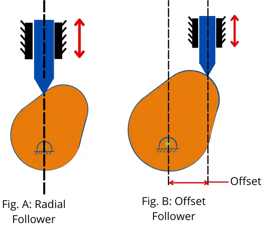
a] Radial follower:- When the follower reciprocates along the axis passing through the center of the cam then such follower is known as a radial follower.
b] Offset follower:- An offset follower is a follower that reciprocates along an axis that is away from the center of the cam.
3] According to motion of follower:-
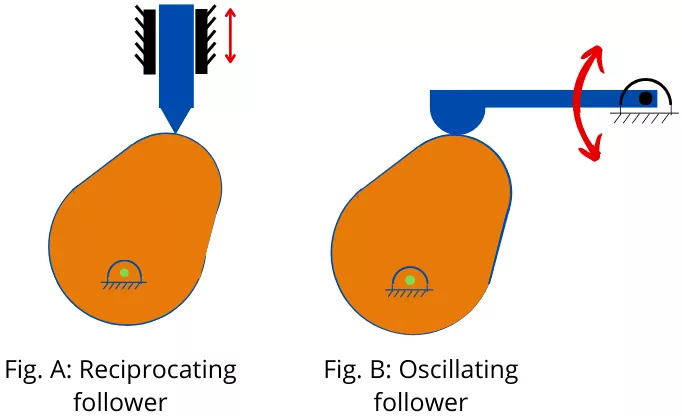
a] Reciprocating follower:- The reciprocating follower reciprocates along a certain axis.
b] Oscillating follower:- This type of follower oscillates in a circular arc around a fixed center point.
Degree of freedom of cam and follower:
The cam and follower mechanism require only one input for its proper functioning, therefore the degree of freedom of this mechanism is one.
For the cam and follower mechanisms with knife-edge follower, the degree of freedom can be found as follows,
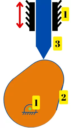
The above mechanism consists of the following three links (𝓁):-
Link 1:- Support
Link 2:- Cam
Link 3:- Follower
The mechanism has 2 lower pairs (J = 2, i.e.1 & 2, 1 & 3), and one higher pair (h = 1, i.e. 2 & 3).
As per the kutzbach criteria, the degree of freedom is given by,
DOF = 3(𝓁 – 1) – 2J – h
DOF = 3(3 – 1) – (2 x 2) – 1
DOF = 1
Thus the cam and follower mechanism has a degree of freedom of 1.
Formulae:
Following are some of the formulae used in the case of the cam and follower mechanism:-
1] Mean speed/velocity of follower:-
For out/rise stroke:-
`V_{\text{o(mean)}}` = `\frac{S\omega}{\theta_{o}}`
For return stroke:-
`V_{\text{R(mean)}}` = `\frac{S\omega}{\theta_{R}}`
Where,
S = Stroke/Lift of follower
ω = Angular speed of cam
`\theta_{o}` = Angle traveled by cam during rise stroke
`\theta_{R}` = Angle traveled by cam during the return stroke
Following are the different formulae base on a different motion of the follower:-
1] Uniform acceleration and retardation:
Dispacement:-
`x_{o}` = `[\frac{2S}{\theta_{o}^{2}}].\theta^{2}`
`x_{R}` = `[\frac{2S}{\theta_{R}^{2}}].\theta^{2}`
Velocity:-
`V_{o}` = `[\frac{4S\omega}{\theta_{o}^{2}}]\theta`
`V_{R}` = `[\frac{4S\omega}{\theta_{R}^{2}}]\theta`
Maximum velocity:-
`V_{\text{o(max)}}` = `[\frac{2S\omega}{\theta_{o}}]`
`V_{\text{R(max)}}` = `[\frac{2S\omega}{\theta_{R}}]`
Acceleration:-
`a_{o}` = `\frac{4S\omega^{2}}{\theta_{o}^{2}`
`a_{R}` = `\frac{4S\omega^{2}}{\theta_{R}^{2}`
2] Simple harmonic motion:-
Displacement:-
`x_{o}` = `\frac{S}{2}` (1 – `cos[\frac{\pi}{\theta_{o}}\theta]`)
`x_{R}` = `\frac{S}{2}` (1 – `cos[\frac{\pi}{\theta_{R}}\theta]`)
Velocity:-
`V_{o}` = `\frac{S\omega\pi}{2\theta_{o}}sin(\frac{\pi}{\theta_{o}}\theta)`
`V_{R}` = `\frac{S\omega\pi}{2\theta_{R}}sin(\frac{\pi}{\theta_{R}}\theta)`
Maximum Velocity:-
`V_{\text{o(max)}}` = `[\frac{S\omega\pi}{2\theta_{o}}]`
`V_{\text{R(max)}}` = `[\frac{S\omega\pi}{2\theta_{R}}]`
Acceleration:-
`a_{o}` = `\frac{S\omega^{2}\pi^{2}}{2\theta_{o}^{2}}.cos[\frac{\pi}{\theta_{o}}\theta]`
`a_{R}` = `\frac{S\omega^{2}\pi^{2}}{2\theta_{R}^{2}}.cos[\frac{\pi}{\theta_{R}}\theta]`
Maximum acceleration:-
`a_{\text{o(max)}}` = `\frac{S\omega^{2}\pi^{2}}{2\theta_{o}^{2}}`
`a_{\text{R(max)}}` = `\frac{S\omega^{2}\pi^{2}}{2\theta_{R}^{2}}`
3] Cycloidal motion:-
Displacement:-
`x_{o}` = `S[\frac{\theta}{\theta_{o}}-\frac{1}{2\pi}sin(2\pi\frac{\theta}{\theta_{o}})]`
`x_{R}` = `S[\frac{\theta}{\theta_{R}}-\frac{1}{2\pi}sin(2\pi\frac{\theta}{\theta_{R}})]`
Velocity:-
`V_{o}` = `\frac{S\omega}{\theta_{o}}[1-cos(2\pi\frac{\theta}{\theta_{o}})]`
`V_{R}` = `\frac{S\omega}{\theta_{R}}[1-cos(2\pi\frac{\theta}{\theta_{R}})]`
Maximum Velocity:-
`V_{\text{o(max)}}` = `\frac{2S\omega}{\theta_{o}}`
`V_{\text{R(max)}}` = `\frac{2S\omega}{\theta_{R}}`
Acceleration:-
`a_{o}` = `\frac{2\pi S\omega^{2}}{\theta_{o}^{2}}sin(2\pi \frac{\theta}{\theta_{o}})`
`a_{R}` = `\frac{2\pi S\omega^{2}}{\theta_{R}^{2}}sin(2\pi \frac{\theta}{\theta_{R}})`
Maximum Acceleration:-
`a_{\text{o(max)}}` = `\frac{2\pi S\omega^{2}}{\theta_{o}^{2}}`
`a_{\text{R(max)}}` = `\frac{2\pi S\omega^{2}}{\theta_{R}^{2}}`
Types of follower motion:
The motion of the follower depends on the profile of the cam. Therefore the cam is designed in such a way that the follower performs anyone of the following motions.
- Uniform velocity
- Uniform acceleration and retardation
- Simple harmonic motion (SHM)
- Cycloidal motion
Let’s discuss each of them in detail.
1] Uniform velocity:-
In this case, during the out stroke and return stroke, the follower moves with a constant velocity.
For the cam with a rise-dwell-return follower, the followers show displacement, velocity, and acceleration varies as follows:
Displacement:-
During the out stroke and return stroke, as the follower moves with a constant velocity, therefore the variation of displacement (`x`) with respect to cam angle (θ) has linear nature.
Velocity:-
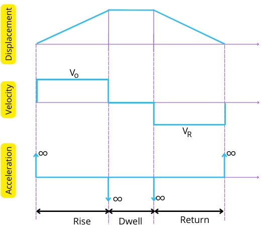
The follower moves with a constant velocity during outward and return strokes and has zero velocity during the dwell period.
Acceleration:-
In this case, during the out and return stroke, the follower moves with constant velocity, so the follower has zero acceleration.
But it is considered that at the start and end of the out stroke, the velocity of the follower instantly increases from zero to `V_{\text{max}}` and decreases from `V_{\text{max}}` to zero respectively. Thus at the start of out stroke and at the end of out stroke, the follower moves with infinite acceleration.
Similarly, at the start of the return stroke and at the end of the return stroke the follower moves with infinite acceleration.
The variation of displacement, velocity, and acceleration for the follower moving with constant velocity are shown in the below graph.
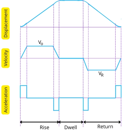
In actual practice, it is not possible to attain infinite acceleration of the follower while the follower takes a certain time to accelerate from rest. Therefore the above graph of the displacement, velocity, and acceleration can be modified as,
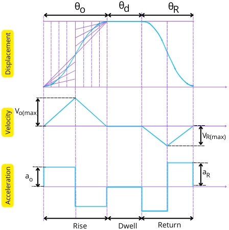
2] Uniform acceleration and retardation:-
In this motion, during the out stroke, the follower uniformly accelerates (0 to `V_{\text{max}}`) within the first half of the stroke, and then it uniformly retards (from `V_{\text{max}}` to 0) in another half of the stroke.
Similarly, during the return stroke, the follower accelerates and deaccelerates for half stroke each respectively.
For this motion, the displacement, velocity, and acceleration of the follower vary as follows:
Displacement:
In this case, during the rise and return stroke, the displacement (`x`) vs cam angle (θ) graph shows parabolic behavior. Thus during the out stroke for the uniform acceleration, the displacement is given by
Displacement (`x_{o}`) ∝ Square of cam angle (θ²)
`x_{o}` ∝ θ²
`x_{o}` = C.θ²
The follower uniformly accelerates for the first half of the out stroke (S/2) as well as within half of the out stroke angle (`\theta_{o}`). Therefore to find value of constant, put `x` = `\frac{S}{2}` and θ = `\frac{\theta_{o}}{2}` in above equation.
∴ `\frac{S}{2}` = C`(\frac{\theta_{o}}{2})^{2}`
∴ C = `\frac{2S}{\theta_{o}^{2}}`
Put the value of C in above equation of displacement (`x_{o}`).
| ∴ `x_{o}` = `[\frac{2S}{\theta_{o}^{2}}].\theta^{2}` |
This is the equation for the displacement of the follower during out stroke.
Similarly, for the return stroke, the equation of the displacement is given by,
| ∴ `x_{R}` = `[\frac{2S}{\theta_{R}^{2}}].\theta^{2}` |
Velocity:
In this motion, during the out and return stroke, the velocity of the follower varies linearly with respect to the cam angle.
The velocity of the follower is given by,
`V_{o}` = `\frac{dx_{o}}{dt}`
`V_{o}` = `\frac{dx_{o}}{d\theta}.\frac{d\theta}{dt}`
`V_{o}` = `\frac{dx_{o}}{d\theta}.ω` —– [∵ ω = `\frac{d\theta}{dt}`]
`V_{o}` = `\frac{d}{d\theta}([\frac{2S}{\theta_{o}^{2}}].\theta^{2})`ω
`V_{o}` = `\frac{2S\omega}{\theta_{o}^{2}}2\theta`
| `V_{o}` = `[\frac{4S\omega}{\theta_{o}^{2}}]\theta` |
This is the equation of velocity for the out stroke movement of the follower.
Similarly, for the return stroke, the equation of velocity of the follower is given by,
| `V_{R}` = `[\frac{4S\omega}{\theta_{R}^{2}}]\theta` |
The maximum velocity of the follower during out stroke is observed when `\theta` = `\frac{\theta_{o}}{2}`
∴`V_{\text{o(max)}}` = `[\frac{4S\omega}{\theta_{o}^{2}}][\frac{\theta_{o}}{2}]`
| `V_{\text{o(max)}}` = `[\frac{2S\omega}{\theta_{o}}]` |
Similarly for return stroke, the maximum velocity of the follower is given by,
| `V_{\text{R(max)}}` = `[\frac{2S\omega}{\theta_{R}}]` |
Acceleration:-
During the out stroke and return stroke, the follower moves with constant acceleration for the first half of the stroke, and further, it moves with constant retardation for the second half of the stroke.
The accleration of the follower during out stroke is given by,
`a_{o}` = `\frac{dV_{o}}{dt}`
`a_{o}` = `\frac{dV_{o}}{d\theta}` x `\frac{d\theta}{dt}`
`a_{o}` = `\frac{dV_{o}}{d\theta} \times \omega` —– [∵ `\omega` = `\frac{d\theta}{dt}`]
`a_{o}` = `\frac{d}{d\theta}{[\frac{4S\omega}{\theta_{o}^[2]}]\theta}\omega`
| `a_{o}` = `\frac{4S\omega^{2}}{\theta_{o}^{2}` |
Similarly for the return stroke, the accleration is given by,
| `a_{R}` = `\frac{4S\omega^{2}}{\theta_{R}^{2}` |
The variation of displacement, velocity, and acceleration for the follower is shown in the below graph.
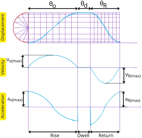
3] Simple harmonic motion (SHM):-
For the simple harmonic motion (SHM) of the follower, the displacement, velocity, and acceleration vary as follows:-
1] Displacement:-
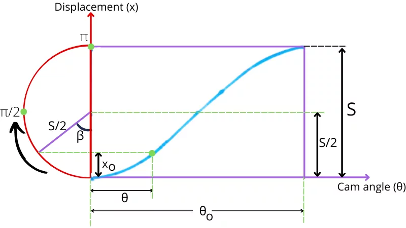
The above figure shows the displacement of the follower with respect to the cam angle for the rise/out stroke. The half-circle in the above diagram indicates the harmonic semicircle.
In the case of a follower moving in SHM, the angle turned by the cam during out stroke (`\theta`) is proportional to the angle turned on harmonic semicircle (`\beta`). As during out stroke, the maximum angle turned by cam is `\theta_{o}` and the maximum angle turned on harmonic semicircle is `\pi`, therefore from the above figure, it can be concluded that,
`\frac{\theta}{\theta_{o}}` = `\frac{\beta}{\pi}`
∴ `\beta` = `\frac{\pi}{\theta_{o}}\theta`
From the above figure, the displacement of the follower during a out stroke is given by,
`x_{o}` = `\frac{S}{2}` – `\frac{S}{2}cos\beta`
`x_{o}` = `\frac{S}{2}` (1 – `cos\beta`)
`x_{o}` = `\frac{S}{2}` (1 – `cos[\frac{\pi}{\theta_{o}}\theta]`)
| `x_{o}` = `\frac{S}{2}` (1 – `cos[\frac{\pi}{\theta_{o}}\theta]`) |
This is the equation for the displacement of the follower during an out stroke with SHM.
Similarly for the return stroke, the displacement of the follower is given by,
| `x_{R}` = `\frac{S}{2}` (1 – `cos[\frac{\pi}{\theta_{R}}\theta]`) |
Velocity:
In SHM, the graph of velocity-cam angle is consist of sine curve.
The velocity of the cam during out stroke is given by,
`V_{o}` = `\frac{dx_{o}}{dt}`
`V_{o}` = `\frac{dx_{o}}{d\theta}.\frac{d\theta}{dt}`
`V_{o}` = `\frac{dx_{o}}{d\theta}\omega`
`V_{o}` = `\frac{d}{d\theta}{\frac{S}{2}[1-cos(\frac{\pi}{\theta_{o}}\theta)]}\omega`
`V_{o}` = `\frac{S\omega}{2}[sin(\frac{\pi}{\theta_{o}}\theta)\frac{\pi}{\theta_{o}}]`
| `V_{o}` = `\frac{S\omega\pi}{2\theta_{o}}sin(\frac{\pi}{\theta_{o}}\theta)` |
This is the equation of velocity (out stroke) of the follower moving with simple harmonic motion.
By performing a similar calculation for the return stroke, the velocity during the return stroke is given by,
| `V_{R}` = `\frac{S\omega\pi}{2\theta_{R}}sin(\frac{\pi}{\theta_{R}}\theta)` |
The velocity of follower becomes maximum when the term sin(`\frac{\pi}{\theta_{R}}\theta`) becomes 1, thus the maximum velocity of the follower is given by,
| `V_{\text{o(max)}}` = `\frac{S\omega\pi}{2\theta_{o}}` –(For out stroke) |
| `V_{\text{R(max)}}` = `\frac{S\omega\pi}{2\theta_{R}}` –(For return stroke) |
Acceleration:-
In SHM, the variation of accleration with respect to cam angle is the cosine curve. The acceleration of follower during out stroke can be find by,
`a_{o}` = `\frac{dV_{o}}{dt}`
`a_{o}` = `\frac{dV_{o}}{d\theta}.\frac{d\theta}{dt}`
`a_{o}` = `\frac{dV_{o}}{d\theta}.\omega`
`a_{o}` = `\frac{d}{dt}[(\frac(S\omega\pi)(2\theta_{o}))sin(\frac{\pi}{\theta_{o}}\theta)].\omega`
`a_{o}` = `\frac{S\omega^{2}\pi}{2\theta_{o}}.cos[\frac{\pi}{\theta_{o}}\theta]\frac{\pi}{\theta_{o}}`
| `a_{o}` = `\frac{S\omega^{2}\pi^{2}}{2\theta_{o}^{2}}.cos[\frac{\pi}{\theta_{o}}\theta]` |
Similarly calculating for the return stroke, the equation for the acceleration is given by,
| `a_{R}` = `\frac{S\omega^{2}\pi^{2}}{2\theta_{R}^{2}}.cos[\frac{\pi}{\theta_{R}}\theta]` |
The acceleration of the follower becomes maximum when the term `cos[\frac{\pi}{\theta_{R}}\theta]` becomes 1,
Thus the maximum accelration during out stroke and return stroke is given by,
| `a_{\text{o(max)}}` = `\frac{S\omega^{2}\pi^{2}}{2\theta_{o}^{2}}` |
| `a_{\text{R(max)}}` = `\frac{S\omega^{2}\pi^{2}}{2\theta_{R}^{2}}` |
The variation of displacement, velocity, and acceleration of follower moving in simple harmonic motion is shown in the below figure.
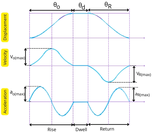
4] Cycloidal motion:-
During the cycloidal motion, the displacement velocity, and acceleration of the follower vary as follows:-
Displacement:-
In this case, the displacement curve for the follower is a cycloid traced by the circle of radius `\frac{S}{2\pi}`.
The equation of displacement for the cycloidal motion of the follower is given by,
For out stroke,
| `x_{o}` = `S[\frac{\theta}{\theta_{o}}-\frac{1}{2\pi}sin(2\pi\frac{\theta}{\theta_{o}})]` |
For return stroke,
| `x_{R}` = `S[\frac{\theta}{\theta_{R}}-\frac{1}{2\pi}sin(2\pi\frac{\theta}{\theta_{R}})]` |
Velocity:-
The velocity of the follower during out stroke is given by,
`V_{o}` = `\frac{dx_{o}}{dt}`
`V_{o}` = `\frac{dx_{o}}{d\theta}` x `\frac{d\theta}{dt}`
`V_{o}` = `\frac{dx_{o}}{d\theta}` x ω
`V_{o}` = `\frac{d}{d\theta}{S[\frac{\theta}{\theta_{o}}-\frac{1}{2\pi}sin(2\pi\frac{\theta}{\theta_{o}})]}\omega`
`V_{o}` = Sω`[\frac{1}{\theta_{o}}[1-cos(2\pi\frac{\theta}{\theta_{o}})]]`
| `V_{o}` = `\frac{S\omega}{\theta_{o}}[1-cos(2\pi\frac{\theta}{\theta_{o}})]` |
This is the equation of velocity for follower moving in cycloidal motion during out stroke. Similarly, the equation of velocity during return stroke is given by,
| `V_{R}` = `\frac{S\omega}{\theta_{R}}[1-cos(2\pi\frac{\theta}{\theta_{R}})]` |
The velocity of the follower becomes maximum when the term cos [`2\pi\frac{\theta}{\theta_{R}}`] becomes -1.
Thus the maximum velocity of the follower during out stroke is given by,
`V_{\text{(o)max}}` = `\frac{S\omega}{\theta_{o}}[1-(-1)]`
| `V_{\text{o(max)}}` = `\frac{2S\omega}{\theta_{o}}` |
This is the equation of maximum velocity of follower during out stroke.
Similarly, the maximum velocity of follower during return stroke is given by,
| `V_{\text{R(max)}}` = `\frac{2S\omega}{\theta_{R}}` |
Acceleration:-
The acceleration of follower during out stroke is given by,
`a_{o}` = `\frac{dV_{o}}{dt}`
`a_{o}` = `\frac{dV_{o}}{d\theta}` x `\frac{d\theta}{dt}`
`a_{o}` = `\frac{dV_{o}}{d\theta}`.ω
`a_{o}` = `\frac{d}{d\theta}{\frac{S\omega}{\theta_{o}}[1-cos(2\pi\frac{\theta}{\theta_{o}})]}`ω
`a_{o}` = `\frac{S\omega^{2}}{\theta_{o}}[sin(2\pi \frac{\theta}{\theta_{o}})\times \frac{2\pi }{\theta_{o}}]`
| `a_{o}` = `\frac{2\pi S\omega^{2}}{\theta_{o}^{2}}sin(2\pi \frac{\theta}{\theta_{o}})` |
This is the acceleration of follower during out stroke moving in cycloidal motion.
Similarly, for the return stroke, the equation of acceleration is given by,
| `a_{R}` = `\frac{2\pi S\omega^{2}}{\theta_{R}^{2}}sin(2\pi \frac{\theta}{\theta_{R}})` |
The acceleration of the follower becomes maximum when sin [`2\pi \frac{\theta}{\theta_{o}}`] becomes 1.
Thus the maximum acceleration during out stroke and return stroke is given by,
| `a_{\text{o(max)}}` = `\frac{2\pi S\omega^{2}}{\theta_{o}^{2}}` |
| `a_{\text{R(max)}}` = `\frac{2\pi S\omega^{2}}{\theta_{R}^{2}}` |
The below figure shows the displacement, velocity, and acceleration of the follower performing the cycloidal motion.
Advantages:
Following are some of the advantages of using the cam-follower mechanism:-
- The cam and follower can obtain various types of motions.
Example:- Rotary to reciprocating, Rotary to oscillatory, Translational to reciprocatory, Translational to oscillating, etc. - It can obtain different motions by properly designing a cam profile.
- The cam and follower mechanism is well known for its accurate operation with minimum or no error.
- It is a compact mechanism to convert rotary motion into reciprocating motion with a minimum number of components.
Disadvantages:
The disadvantages of using the cam and follower mechanism are as follows:-
- Higher wear rate
- Manufacturing of the cam is complex
- Higher cost of manufacturing
- Not suitable for transmitting higher forces
- The stroke length of the follower is limited.
Applications:
Following are some of the real-life applications of the cam and follower mechanism:-
- Operating of valves in IC engine:- The inlet and exhaust valves in the IC engine are controlled with the help of a cam and follower mechanism.
- The inline fuel injection pump in diesel engines uses a cam and follower mechanism to pump fuel.
- The feed mechanism in the automatic lathe machine uses a cam and follower mechanism.
- Printing machines
- Wall clock and toys
Cam and follower solved examples:
| 1. A disc cam rotating at 1440 rpm reciprocates the follower in cycloidal motion. The follower has a total lift of 20 mm. If the angle of rise is 120° and the angle of return is 100° then find the velocity and acceleration of the follower at the mid of the out stroke and return stroke. |
Given:-
S = 20 mm
N = 1440 rpm
`\theta_{o}` = 120° = 2.094 radian
`\theta_{R}` = 100° = 1.745 radian
`x_{o}` = `x_{R}` = `\frac{S}{2}` = `\frac{20}{2}` = 10 mm
Solution:
The angular speed of the cam is given by,
ω = `\frac{2\pi N}{60}` = `\frac{2\pi \times 1440}{60}` = 150.796 rad/s
1] For out stroke:-
For cycliodal motion, the displacement of the follower during out stroke is given by,
`x_{o}` = `S[\frac{\theta }{\theta_{o}}-\frac{1}{2\pi}sin(2\pi \frac{\theta }{\theta_{o}})]`
10 = `20[\frac{\theta }{2.094}-\frac{1}{2\pi }sin(2\pi \frac{\theta }{2.094})]`
θ = 1.047 radian
Thus the velocity of follower ar the mid of out stroke is given by,
`V_{o}` = `\frac{S\omega }{\theta_{o}}[1-cos2\pi \frac{\theta }{\theta_{o}}]`
`V_{o}` = `\frac{20 \times 150.796}{2.094}[1-cos(2\pi \frac{1.047}{2.094})]`
| `\mathbf{V_{o}}` = 2880.534 mm/s |
Acceleration of follower at the mid of out stroke is given by,
`a_{o}` = `\frac{2\pi S \omega ^{2}}{\theta_{o}^{2}}sin(2\pi \frac{\theta }{\theta_{o}})`
`a_{o}` = `\frac{2\pi \times 20 \times 150.796^{2}}{2.094^{2}}sin(2\pi \frac{1.047}{2.094})`
| `\mathbf{a_{o}}` = 0 mm/s² |
2] For return stroke:-
For cycloidal motion, the displacement during the return stroke is given by,
`x_{R}` = `S[\frac{\theta}{\theta_{R}}-\frac{1}{2\pi}sin(2\pi\frac{\theta}{\theta_{R}})]`
10 = `20[\frac{\theta}{1.745}-\frac{1}{2\pi}sin(2\pi\frac{\theta}{1.745})]`
θ = 0.8725 radian
Thus the velocity of follower at the of return stroke is given by,
`V_{R}` = `\frac{S\omega }{\theta_{R}}[1-cos(2\pi \frac{\theta}{\theta_{R}})]`
`V_{R}` = `\frac{20 \times 150.796}{1.745}[1-cos(2\pi \frac{0.8725}{1.745})]`
| `\mathbf{V_{R}}` = 3456.641 mm/s |
The acceleration of follower at the mid of return stroke is given by,
`a_{R}` = `\frac{2\pi S\omega^{2}}{\theta_{R}^{2}}sin(2\pi \frac{\theta}{\theta_{R}})`
`a_{R}` = `\frac{2\pi \times 20 \times 150.796^{2}}{1.745^{2}}[sin(2\pi \frac{0.8725}{1.745})]`
| `\mathbf{a_{R}}` = 0 mm/s² |
| 2. A cam rotating at the speed of 900 rpm helps to reciprocate the follower with constant acceleration and retardation. The angle of rise of a follower is 90° and the angle of return is 110°. If the total lift of the follower is 30 mm then find, 1] Mean velocity of follower during rise and return stroke. 2] Maximum velocity and maximum acceleration during out stroke. |
Given:-
N = 900 rpm
`\theta_{o}` = 90° = 1.57 radian
`\theta_{R}` = 110° = 1.919 radian
S = 30 mm
Solution:
The angular velocity of the cam is given by,
ω = `\frac{2\pi N}{60}` = `\frac{2\pi \times 900}{60}` = 94.24 rad/s
1] Mean velocity of follower:-
During out stroke, the mean velocity of the follower is given by,
`V_{\text{o(mean)}}` = `\frac{S\omega }{\theta_{o}}`
`V_{\text{o(mean)}}` = `\frac{30 \times 94.24}{1.57}`
| `\mathbf{V_{\text{o(mean)}}}` = 1800.7 mm/s |
During return stroke, the mean velocity of the follower is given by,
`V_{\text{R(mean)}}` = `\frac{S\omega }{\theta_{R}}`
`V_{\text{R(mean)}}` = `\frac{30 \times 94.24}{1.919}`
| `\mathbf{V_{\text{R(mean)}}}` = 1473.26 mm/s |
2] Maximum velocity and acceleration during out stroke:-
For the follower moving with constant acceleration and retardation, the maximum velocity is given by,
`V_{\text{o(max)}}` = `\frac{2S\omega }{\theta_{o}}`
`V_{\text{o(max)}}` = `\frac{2 \times 30 \times 94.24}{1.57}`
| `\mathbf{V_{\text{o(max)}}}` = 3601.52 mm/s |
For uniform acceleration and retardation, the maximum acceleration of follower during out stroke is given by,
`a_{\text{o(max)}}` = `a_{o}`
`a_{\text{o(max)}}` = `\frac{4S\omega^{2}}{\theta_{o}^{2}}`
`a_{\text{o(max)}}` = `\frac{4 \times 30 \times 94.24^{2}}{1.57^{2}}`
| `\mathbf{a_{\text{o(max)}}}` = 432.36 x 10³ mm/s² |
FAQs:
-
Where is a cam and follower used?
The cam and follower are used in the following applications:
1] Operating valves in IC engine
2] Inline fuel injection pump
3] Clocks, etc. -
What is the difference between a cam and follower?
The basic difference between the cam and follower is that the cam is a driving member that rotates at a constant speed while the follower is the driven member whose motion is predetermined by the profile of the cam.
-
What are the types of follower?
Depending on the shape, the followers are classified as follows,
1] Knife-edge follower
2] Flat follower
3] Roller follower
4] Spherical end follower
Based on the motion, the followers are classified as follows,
1] Reciprocating follower
2] Oscillating follower. -
Why is Cam important?
The cam and follower are important because they can operate at high speed with high accuracy of operation.
-
Which type of cam and follower is used in the ic engine?
Radial type cam and flat face follower are used in ic engine.
The unique features of the cam and follower mechanism make it suitable for use in different applications. We hope that the above information about the cam and follower was helpful to you. If you like the above post, then check out our other articles too.
You may like to read: