What is the Diesel cycle?
The diesel cycle is an ideal gas power cycle developed by the German inventor Rudolf Diesel in 1897.
The diesel engines are working on the principle of this diesel cycle. This cycle uses a higher compression ratio from 14:1 to 22:1.
The ideal diesel cycle consists of four processes that include two isentropic, one constant pressure, and one constant volume process.
Contents:
Diesel cycle PV and TS diagram:
The diesel cycle can be plotted on PV and TS plots as shown below,
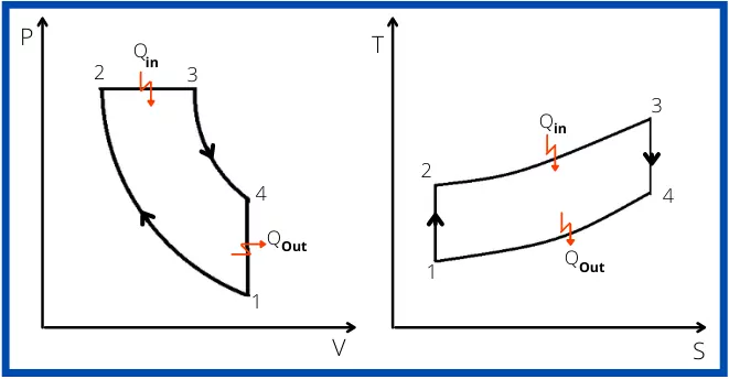
Each process of the diesel cycle is described as,
Process 1-2:- Isentropic compression
In this process, the charge taken during suction stroke is compressed adiabatically from volume V1 to V2.
Process 2-3:- Constant pressure heat addition
After the compression of the intake air, the heat is added at constant pressure. This process indicates, the fuel injection period in diesel engines.
Process 3-4:- Isentropic expansion
The higher pressure generated inside of the engine is used for the work of expansion from state 3 to state 4.
In this process, the pressure of the air is reduced from P3 to P4 and the volume increases from V3 to V4.
Process 4-1:- Constant volume heat rejection
In this process, the heat from the air is rejected isochorically to lower the temperature from T4 to T1.
Different terms used in the diesel cycle:
1] Cut-off ratio:-
In the diesel cycle, the cut-off ratio is the ratio of volume after the heat is added to the volume before heat addition. Or
It is also defined as the ratio of volume when fuel injection is cut-off to the volume when fuel injection starts.
From the PV diagram, it can be written as,
`r_{c}=\frac{V_{3}}{V_{2}}`
2] Compression ratio:-
The compression ratio is the ratio of volume before the compression to the volume of charge after compression. Or
It is also defined as the ratio of the total volume of a cylinder to the clearance volume.
From the PV diagram, it is written as,
`r_{c}=\frac{V_{1}}{V_{2}}=\frac{V_{\text{Stroke}}+V_{\text{Clearance}}}{V_{\text{Clearance}}}`
3] Expansion ratio:-
It is the ratio is volume after the expansion to the volume before expansion process.
From the PV diagram, it is stated as,
`r_{e}=\frac{V_{4}}{V_{3}}`
It is also expressed as,
`r_{e}=\frac{V_{4}}{V_{3}}\times \frac{V_{2}}{V_{2}}`
`r_{e}=\frac{V_{4}/V_{2}}{V_{3}/V_{2}}`
`r_{e}=\frac{V_{1}/V_{2}}{V_{3}/V_{2}} \cdots [\therefore V_{1} = V_{4}]`
`r_{e}=\frac{r_{k}}{r_{c}}`
Diesel cycle analysis:
It contains the study of each process to find the work done, heat transfer, and change in internal energy for each cycle.
Process 1-2:- Isentropic compression
As process 1-2 is isentropic therefore heat transfer in this process is zero.
`Q_{1-2}=0`
The change in internal energy for this process is given by,
`du_{1-2}=C_{v}(T_{2}-T_{1})`
By using the first law of thermodynamics,
`Q_{1-2} = du_{1-2} + W_{1-2}`
`0=C_{V}(T_{2}-T_{1})+W_{1-2}`
`\therefore W_{1-2}=C_{v}(T_{1}-T_{2})`
Process 2-3:- Constant pressure heat addition
For the constant pressure process, the rate of heat transfer is equal to the change in enthalpy,
`Q_{2-3} = C_{p}(T_{3}-T_{2})`
The change in internal energy for the process 2-3 is given by,
`du_{2-3} = C_{v}(T_{3}-T_{2})`
Now by using the first law of thermodynamics for the process 2-3,
`Q_{2-3}=du_{2-3}+W_{2-3}`
`C_{p}(T_{3}-T_{2})=C_{V}(T_{3}-T_{2})+W_{2-3}`
`W_{2-3}=(C_{P}-C_{V})(T_{3}-T_{2})`
`W_{2-3}=R(T_{3}-T_{2}) \cdots [\because R=C_{P}]`
Or for constant pressure process 2-3, the workdone is also given by,
`W_{2-3}=P_{2}(V_{3}-V_{2})`
Process 3-4:- Isentropic expansion
As process 3-4 is an isentropic process
`\text{Therefore,}\ Q_{3-4} = 0`
The change in internal energy for this process is given by,
`du_{3-4} = C_{V}(T_{4}-T_{3})`
Now by using the first law of thermodynamics,
`Q_{3-4}=du_{3-4}+W_{3-4}`
`0=C_{V}(T_{4}-T_{3})+W_{3-4}`
`\therefore W_{3-4}=C_{v}(T_{3}-T_{4})`
Process 4-1:- Constant volume heat rejection
For the constant volume process, there is no workdone is done or gained by the process.
`\therefore W_{4-1} = 0`
The change in internal energy for the process 4-1 is given by,
`du_{4-1} = C_{V}(T_{1}-T_{4})`
The first law of thermodynamics for the process 4-1 can be written as
`Q_{4-1} = du_{4-1}+W_{4-1}`
`Q_{4-1}=Cv(T_{1}-T_{4})+0`
`Q_{4-1}=Cv(T_{1}-T_{4})`
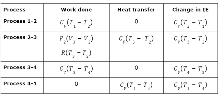
The above results for each process are summarised in the below table,
All parameters are summarized below:
Diesel cycle work done:
The Net work done from the diesel cycle is given by,
WNet = QNet
WNet = Q2-3 + Q4-1
WNet = CP(T3 – T2) + CV(T1 – T4)
Diesel cycle efficiency derivation:
The thermal efficiency of the diesel cycle is the ratio of net work to the heat supplied.
For diesel cycle,
`\therefore \eta=\frac{W_{Net}}{Q_{ \text{Supplied}}}`
`\eta=\frac{W_{Net}}{Q_{2-3}}`
`\eta=\frac{C_{P}(T_{3}-T_{2})+C_{V}(T_{1}-T_{4})}{C_{P}(T_{3}-T_{2})}`
`\eta=1+\frac{C_{V}(T_{1}-T_{4})}{C_{p}(T_{3}-T_{2})}`
`\eta=1+\frac{(T_{1}-T_{4})}{r.(T_{3}-T_{2})} \cdots \mathbf{\text{[Equation-1]}}`
For isentropic process 1-2, the relation between T1 and T2 is given by,
`\frac{T_{2}}{T_{1}}=(\frac{V_{1}}{V_{2}})^{r-1}`
`\frac{T_{2}}{T_{1}}=r_{K}^{r-1}\cdots [\because r_{k} = \frac{V_{1}}{V_{2}}]`
`T_{2} = r_{K}^{r-1} \cdots \mathbf{\text{[Equation-2]}}`
For the process 2-3, the relation between temperature T2 and T3 is given by,
`\frac{T_{3}}{T_{2}}=\frac{V_{3}}{V_{2}}`
`T_{3}=T_{2}(r_{c}) \cdots [\because r_{c} = \frac{V_{3}}{V_{2}}]`
Putting the value of T1 from equation-1,
`T_{3} = r_{k}^{r-1}.r_{c}.T_{1} \cdots \mathbf{\text{[Equation-3]}}`
For isentropic process 3-4, the relation between temperature T3 and T4 is given by,
`\frac{T_{4}}{T_{3}}=(\frac{V_{3}}{V_{4}})^{r-1}`
`T_{4}=T_{3}(\frac{1}{r_{e}})^{r-1} \cdots [\because r_{e} = \frac{V_{4}}{V_{3}}]`
`T_{4}=T_{3}(\frac{1}{\frac{r_{k}}{r_{c}}})^{r-1} \cdots [\because r_{k} = r_{e}.r_{c}]`
`T_{4}=T_{3}({\frac{r_{c}}{r_{k}}})^{r-1}`
Put the value of T3 from equation-3,
`T_{4}=r_{k}^{r-1}.r_{c}.T_{1}.({\frac{r_{c}}{r_{k}}})^{r-1}`
`T_{4} = T_{1}.r_{c}^{\gamma } \cdots \mathbf{\text{[Equation-4]}}`
Put the value of T2, T3 and T4 in equation 1,
`\eta=1-\frac{(T_{1}.r_{c}^{\gamma })-T_{1}}{r[(r_{k}^{\gamma -1}.r_{c}.T_{1})-(r_{k}^{\gamma -1}.T_{1})]}`
`\eta=1-\frac{r_{c}^{\gamma }-1}{r[r_{k}^{\gamma -1}.r_{c}-r_{k}^{\gamma -1}]}`
`\eta=1-\frac{1}{\gamma }.\frac{1}{r_{k}^{\gamma -1}}.\frac{r_{c}^{\gamma }-1}{r_{c}^{\gamma }-1}`
This is the equation for the thermal efficiency of the Diesel cycle.
Read also: