The gas turbine is a continuous flow IC engine found in various applications. There are different methods are used to improve its efficiency. In this article, we are discussing one of these techniques, regeneration.
Continue reading below to know about method of regeneration in detail.
Contents:
What is regeneration in gas turbine?
Regeneration in gas turbines is the recycling process in which heat energy loss with exhaust gases from the turbine is utilized to heat the air after compression.
The hot gases exhausted by the turbine have high heat energy, therefore by using this method we save the loss of heat energy by utilizing it.
In this method, a regenerator installed is one of the heat exchangers. It helps to transfer the heat of exhaust gases to the compressed air before entering into the combustion chamber.
The advantage of implementing this method is that less heat supply is required to heat the air in the combustion chamber, hence less amount of fuel is required.
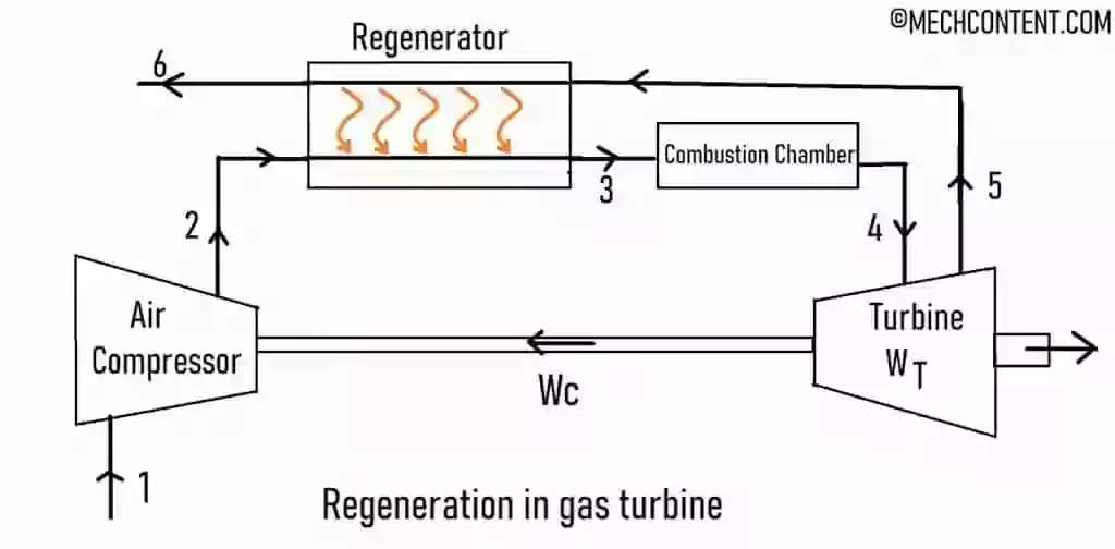
Working of Regeneration in gas turbine:
The compressor takes air from the atmosphere and compresses it to the high temperature and pressure.
After the compressor, the regenerator adds the heat of turbine exhaust gases to compressed air.
The air from the regenerator further flows to the combustion chamber, where fuel directly mixes with the high pressure preheated air. The high-pressure hot gases from the combustion chamber further strikes on the turbine blades to obtain work at turbine output.
After passes through the turbine, these hot gases pass through the regenerator, where their heat energy is transferred to the fresh compressed air.
Regeneration system on TS diagram:
Below figure shows the TS diagram for the working of gas turbine. The process 2-3 and process 5-6 in this cycle, are carried out in the regenerator.
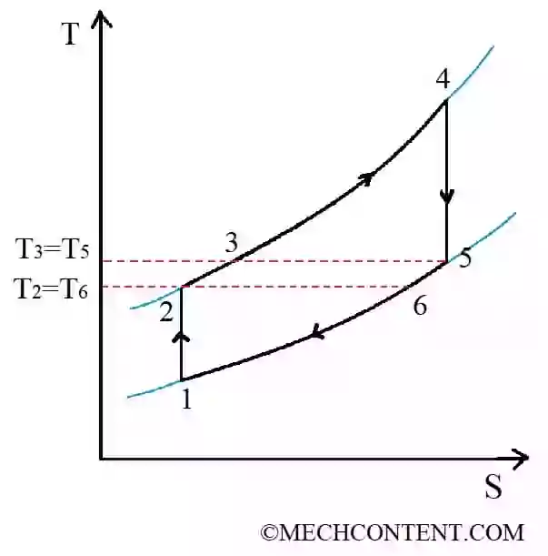
The different processes in the above gas turbine cycle are as follows:
- 1-2 :- Isentropic compression
- 2-3 :- Constant pressure heat addition
- 3-4 :- Constant pressure heat addition
- 4-5 :- Isentropic expansion
- 5-6-1 :- Constant pressure heat rejection [5-6: heat lost to preheat the compressed air]
Efficiency calculation:
The efficiency of the gas turbine is given by,
`\eta=\frac{W_{\text{Turbine}}-W_{\text{Compressor}}}{Q_{s}}`
Work developed by turbine is given by,
`W_{\text{Turbine}}= mC_{p}(T_4-T_5)`
Work to drive the compressor is given by,
`W_{\text{Compressor}}= mC_{p}(T_2-T_1)`
Heat supplied to the air in the combustion chamber is given by,
`Q_{s}= mC_{p}(T_4-T_3)`
Hence, efficiency (`eta`) is given by,
`\eta=\frac{mC_{p}(T_4-T_5)-mC_{p}(T_2-T_1)}{mC_{p}(T_4-T_3)}`
As T5 = T3, therefore, efficiency of theoretical regeneration cycle is by,
`eta = 1-frac{(T_2-T_1)}{(T_4-T_3)}`
FAQ’s:
-
Why is regeneration used in gas turbine power plant?
In a regenerative system, heat energy loss with exhaust gases from the turbine is utilized to heat the fresh air after compression, resulting in increasing efficiency of the plant.
Read also: