Vapour absorption refrigeration system is quite similar to the Vapour compression refrigeration (VCR) system as it replaces the compressor in VCR with the absorber, pump, and generator.
Let’s deep dive into what this system is, its construction, working, and much more details.
Contents:
What is Vapour absorption refrigeration system?
A Vapour absorption refrigeration system (VARS) is a kind of refrigeration in which after evaporation the vapours of refrigerant are absorbed in an absorber solution.
The simple VARS system consists of the following components: Absorber, Pump, Generator, Pressure relief valve, Condenser, Expansion device, and Evaporator.
This kind of refrigeration is used in bigger plants to handle larger refrigeration loads. In such plants, the generator is run with the help of waste heat from the boilers, turbine exhaust steam, waste heat from D.G., etc. Sometimes it also uses solar energy for the generator.
Thus the more considerable power required for the compression of the refrigerant vapour (As in vapour compression refrigeration) is avoided in this system.
The VARS refrigeration system uses two working fluids for refrigeration i.e. refrigerant and absorbent. In the NH3 – H2O refrigeration system, ammonia (NH3) is used as a refrigerant while water (H2O) is used as an absorbent. In H2O – LiBr, VARS refrigeration water is used as a refrigerant while the LiBr is used as an absorbent.
Construction:
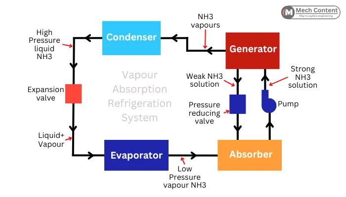
The vapour absorption refrigeration system consists of the following components:-
A) Absorber:-
The purpose of the absorber is to absorb the low-pressure refrigerant vapours in the solution of the refrigerant and absorbent.
The weaker solution from the generator and the low-pressure refrigerant vapours from the evaporator enters the absorber. Here the refrigerant vapours are absorbed to form a stronger solution.
During the absorption, the vapours of the refrigerant lose the latent heat to change their phase from vapour to liquid. Thus it raises the temperature inside the absorber which can lower the absorption capacity of the absorbent. To avoid this, the solution is cooled with the help of cooling water.
B) Pump:- It is used to suck the strong solution from the absorber & deliver it to the generator at higher pressure.
C) Generator:- It is used to heat the strong solution by use of heating coils, solar energy or waste heat. As the refrigerant has a lower boiling point than the absorbent, the refrigerant inside the solution gets vapourised leaving the solution weaker.
If this weak solution goes to the condenser, it may damage the system. Hence the weak solution from the generator returns to the absorber through pressure reducing valve (PRV).
D) Pressure reducing valve (PRV):- The pressure-reducing valve is connected between the generator (works at high pressure) and absorber (works at low pressure). It lowers the pressure of weak solution coming from the generator and then it is passed to the absorber.
E) Condenser:- The high-pressure refrigerant vapours from the generator enter the condenser. The condenser has a cooling medium to cool the hot vapours of the refrigerant. Here the refrigerant vapours get converted into the high-pressure saturated liquid refrigerant.
F) Expansion valve:- Expansion valve is located between the condenser & evaporator. After the condenser, the high-pressure liquid refrigerant enters the expansion valve. Here the high-pressure liquid refrigerant is converted into a mixture of low-pressure refrigerant (liquid + vapour).
G) Evaporator:- The evaporator is located in the enclosed space where cooling is carried out. In the evaporator, the low-pressure liquid refrigerant absorbs the heat in the enclosed space to provide a cooling effect. due to the absorption of heat, the liquid refrigerant gets converted into low-pressure refrigerant vapours.
Vapour absorption refrigeration system working:
The below diagram indicates aqua-ammonia (H2O-NH3) vapour absorption refrigeration system. Here the ammonia is used as a refrigerant while the water is used as an absorbent.
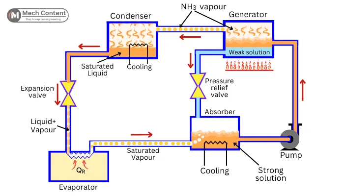
The VARS system works in the following manner:-
Step 1: Absorption in an absorber
The refrigerant vapours from (NH3) the evaporator enter the absorber and get absorbed into the solution of the absorbent and refrigerant (H2O+NH3). Thus it prepares a strong solution of refrigerant and absorbent.
This strong solution is pumped at higher pressure into the generator with the help of a pump.
Step 2: Regeneration
In the generator, the strong solution at high pressure is heated to evolve more than 80% of the refrigerant vapours from the solution. These vapours are sent to the condenser.
After the removal of the refrigerant vapours, the solution (Refrigerent+Absorbent) becomes weaker. The weak solution in the generator is returned to the absorber through pressure reducing valve.
Step 3: Condensation of refrigerant vapours
When High-Pressure Vapour NH3 enters the condenser, the condenser removes the heat from the vapour NH3 with the help of a Cooling Medium.
In the condenser, the refrigerant changes its form from vapour to saturated liquid by leaving the latent heat in the cooling medium.
Step 4: Expansion of the refrigerant
After the condensation, the high-pressure liquid refrigerant enters into the expansion valve, where it gets expands and is converted into a low-pressure mixture of saturated liquid and saturated vapour of refrigerant.
Step 5: Evaporation or refrigerant
In the evaporator, the refrigerant absorbs the heat coming from the enclosed space (To be cooled) thus the saturated liquid refrigerant gets completely converted into the refrigerant vapours.
After the evaporator, low-pressure refrigerant vapours again enter the absorber. Hence in this way, the cycle continues and provides cooling to the enclosed room.
Types of VARS:
The vapour absorption refrigeration system (VARS) can be classified as follows:-
A] Based on the working fluids:-
1) Aqua ammonia: In this VARS system, the water is used as an absorbent, and ammonia is used as a refrigerant. This system can produce a temperature below 0° Celcius, thus it is used for the purpose of refrigeration.
2) LiBr-H2O: Here the LiBr is used as an absorbent and water is used as a refrigerant. As the water freezes at 0° Celsius, this system is used for air-conditioning and for chilling purposes.
B] Based on the number of stages:-
1) Single effect VARS system: The single effect uses a single generator thus the regeneration is carried out in a single stage. It has a lower COP in comparison with the double-effect VARS system.
2) Double effect VARS system: The double effect VARS system has two generators, thus the regeneration takes place in two stages. It has higher COP in comparison with the single effect system.
COP of vapour absorption refrigeration system:
The below figure shows the energy transfer in the VARS refrigeration system:-
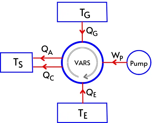
Where,
QG = heat supplied to the generator
TG = Temperature at generator
QE = Heat gained at evaporator
TE = Temperature at evaporator
QA = Heat rejected from absorber
QC = Heat rejected from condenser
TS = Surrounding temperature
The COP of the VARS can be given by,
`\text{COP}=\frac{\text{Required effect}}{\text{Heat supplied}}`
`\therefore COP=\frac{Q_{E}}{Q_{G}} \cdots \text{[Equation 1]}`
As per the first law of thermodynamics, for the closed cycle,
`Q_{Net}=W_{Net}`
`Q_{G}+Q_{E}-Q_{A}-Q_{C}=-W_{P}`
As the pump has negligible work, thus `W_{P} \approx 0`.
`\therefore Q_{G}+Q_{E}-Q_{A}-Q_{C}=0`
`Q_{A}+Q_{C}=Q_{G}+Q_{E} \cdots \text{[Equation 2]}`
For the reversible process, the change in entropy of the universe is zero.
`\therefore \DeltaS_{universe}=0`
`\DeltaS_{\text{Generator}}+\DeltaS_{\text{Evaporator}}-\DeltaS_{\text{Condenser}}-\DeltaS_{\text{Absorber}}=0`
`\frac{Q_{G}}{T_{G}}+\frac{Q_{E}}{T_{E}}-\frac{Q_{C}}{T_{S}}-\frac{Q_{A}}{T_{S}}=0`
`\frac{Q_{G}}{T_{G}}+\frac{Q_{E}}{T_{E}}=\frac{Q_{A}+Q_{C}}{T_{S}}`
As per Equation 2,
`\frac{Q_{G}}{T_{G}}+\frac{Q_{E}}{T_{E}}=\frac{Q_{G}+Q_{E}}{T_{S}}`
`\frac{Q_{G}}{T_{G}}-\frac{Q_{G}}{T_{S}}=\frac{Q_{E}}{T_{S}}-\frac{Q_{E}}{T_{E}}`
`Q_{G}.[\frac{1}{T_{G}}-\frac{1}{T_{S}}]=Q_{E}.[\frac{1}{T_{S}}-\frac{1}{T_{E}}]`
`Q_{G}.[\frac{T_{S}-T_{G]}{T_{G}.T_{S}}]=Q_{E}.[\frac{T_{E}-T_{S}}{T_{E}.T_{S}}]`
`\frac{Q_{E}}{Q_{G}}=[\frac{T_{S}-T_{G]}{T_{G}}].[\frac{T_{E}}{T_{E}-T_{S}}]`
The equation can also written as,
`\frac{Q_{E}}{Q_{G}}=[\frac{T_{G}-T_{S}}{T_{G}}].[\frac{T_{E}}{T_{S}-T_{E}}]`
`\text{As per Equation 1,} \frac{Q_{E}}{Q_{G}} \text{indicates the COP of the VARS system.}`
`\therefore COP_{VARS}=[\frac{T_{G}-T_{S}}{T_{G}}].[\frac{T_{E}}{T_{S}-T_{E}}]`
This is the equation to find the maximum COP of the VAR system.
Advantages:
The following are the advantages of the vapour absorption refrigeration system:-
- It can utilize solar energy or any waste heat from the furnace or turbine for the heating in the generator.
- The refrigerant won’t produce the greenhouse effect.
- The moving component is a pump which consumes less power than the compressor.
- It has a quieter operation.
- It can handle huge refrigeration loads.
Disadvantages:
The following are the disadvantages of vapour absorption refrigeration system:-
- It uses more components than the VCR system.
- It has a bulky setup.
- Lower coefficient of performance (COP).
- The Li-Br absorbent is corrosive in nature.
- Higher initial cost.
Applications:
The vapour absorption refrigeration system has the following applications:-
- Large-capacity refrigeration in bigger plants.
- Suitable for larger air conditioning or water chilling.
- Used in places having electricity problems for refrigeration and air conditioning.
- Electrolux refrigerator.
- VAM chiller
Read also: