An anti-lock braking system is a system that is used to avoid skidding of the wheel (avoids locking of wheel) by rapid braking action. Hence the driver can safely stop the vehicle or take a turn without losing control of the vehicle.
Generally, in vehicles without ABS, when a driver presses the brake pedal, due to braking, the wheel immediately gets locked. But as the vehicle is still in motion, there are chances of a skidding wheel on the road.
So in case, suddenly a big barrier comes in front of the vehicle and if the driver presses the brake pedal hard then due to skidding of a wheel, the driver loses control over the vehicle.
Continue reading to learn more about its principle, construction, working, etc.
In this article, we’re going to discuss:
- What is an Anti-lock braking system (ABS)?
- Anti-lock braking system construction:
- Anti-lock braking system working:
- Advantages:
- Anti-lock braking system applications:
What is an Anti-lock braking system (ABS)?
The ABS system works to keep the deceleration of the wheel normal during braking. In the case of wheel locking, the wheel stops earlier than normal. Hence the sensor considers it as an abnormal deceleration of the wheel and detects the wheel is locked.
As the sensor detects the locking of the wheel, the system releases the brake on the wheel to cause the wheel to rotate to avoid skidding. Then again the sensor sends a signal to apply brakes to the wheel.
This cycle of applying and releasing the brakes continues until the wheel stops.
Therefore by ABS, even if the driver suddenly presses the brakes, the driver can easily reduce the vehicle’s speed and change the direction of the vehicle without skidding.
In easy language, ABS helps to stop the constant locking of a vehicle wheel, hence resulting in vehicle stops without the skidding of a wheel.
Anti-lock braking system construction:
The below figure shows the basic structure of the anti-lock braking system.
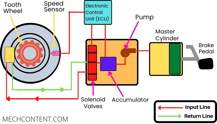
ABS system consists of the following key components:-
1) Master cylinder:-
It is a device that is used to pump the brake fluid and it consists of a piston, brake fluid, and return spring.
The piston rod is connected to the brake pedal hence when the driver presses the brake pedal, the piston presses the brake fluid inside the master cylinder.
The oil reservoir is connected to the master cylinder, which maintains the oil quantity inside the system. The outlet of the master cylinder is connected to the hydraulic control unit.
2) Hydraulic control unit (HCU):-
It is a control unit that works as per signals received from an electronic control unit (ECU). So, as per ECU signals, the hydraulic control unit (HCU) sends the brake fluid through the input line or stops the flow, or take returns the brake fluid from the return lines to apply and release the brake to prevent the wheel from constant locking during braking.
HCU consists of the following components:-
i) Pump
ii) Accumulator
iii) Solenoid Valves
i) Pump:- The Inlet of the pump is connected to the master cylinder and the outlet is connected to the accumulator. The pump pressurizes the brake fluid received from the master cylinder & sends it to the accumulator.
ii) Accumulator:- It is a storage device, which is used to store the pressurized brake fluid. The outlet of the accumulator is connected to the solenoid valves.
iii) Solenoid valves:- Solenoid valves work as per signal received from the ECU to:
- Supply pressurized brake fluid (to apply the brake)
- Stop the supply of brake fluid
- Take return flow of brake fluid to release brake force on the wheel.
3) Electronic control unit (ECU):-
It is a control unit, which receives a signal from the speed sensor & sends signals to components (Accumulator, Solenoid valves, Pump, Master cylinder) to perform required operations when a brake is applied.
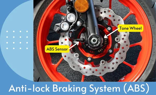
4) Tooth wheel & speed sensor:-
These devices help ECU to know about the wheel speed. The tooth wheel is connected to the wheel & rotates with the wheel.
The speed sensor is also located behind the tooth wheel. It senses the rotation of the tooth wheel & sends the signal to the ECU. So ECU gets data about the vehicle speed and deceleration through the speed sensor.
Anti-lock braking system working:
The ABS works as per the following steps:-
STEP-1:-
When the driver presses the brake pedal, the piston presses the brake fluid & then ECU sends a signal to the solenoid valve & pump to start the flow of brake fluid towards the brake drum.
Hence Brake fluid flows from – Master cylinder -> Pump -> Accumulator -> Solenoid valves -> Brake drum and wheel stops.
STEP-2:-
When the wheel locks due to a brake, the speed sensor sends a signal to ECU. ECU sends a signal to the pump & solenoid valve to stop brake fluid flow & release pressure on the wheel (by returning the brake fluid through the return line).
Therefore brake fluid flows from the Brake drum -> Solenoid valves -> Accumulator and the resulting wheel again starts to rotate.
STEP-3:-
Again speed sensor sends a signal to the ECU about wheel speed. Again ECU sends a signal to the solenoid valve & pump to start the flow, Hence again brake fluid flows from – Pump -> Accumulator -> Solenoid valves -> Wheel Drum
This step occurs rapidly till vehicle speed reduces or the vehicle stops without skidding.
Advantages:
The advantages of using the Anti-lock braking system are as follows:-
- Less braking distance
- Good steering control, so the vehicle can turn in the desired direction
- Avoids accidents.
Anti-lock braking system applications:
The ABS has the following applications:-
- Bike
- Car
Read also: