The brake master cylinder is the heart of the hydraulic braking system as it helps to pump the brake fluid into the brake system. It is operated manually with the help of a foot pedal or by the hand lever with the minimum effort.
In this article, we are discussing the brake master cylinder in detail.
In this article, we’re going to discuss:
- What is Brake master cylinder?
- Brake master cylinder functions:
- Brake master cylinder parts:
- Types of brake master cylinder:
- Brake master cylinder working:
What is Brake master cylinder?
Brake master cylinder is the pumping element in the hydraulic braking system that uses efforts applied on the brake pedal to develop hydraulic pressure in the brake lines.
At the end of the brake line, this hydraulic pressure is used by wheel cylinders to apply braking efforts on all wheels.
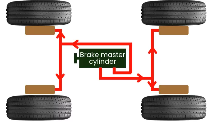
The position of the brake master cylinder in the braking system line diagram is shown below,
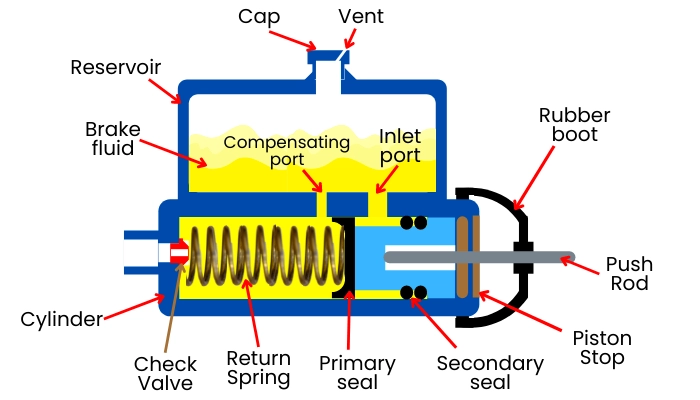
The brake master cylinder generally consists of two sections: The reservoir section and the cylinder section.
The reservoir section above the cylinder supplies the brake fluid to the cylinder through the intake port and receives the excessive oil through compensating port.
The cylinder section pumps the brake fluid to the brake lines when the brake pedal is pressed and receives the brake fluid from the brake line after the brake pedal is released.
Brake master cylinder functions:
Following are some important functions of the brake master cylinder:
a] Pumping of brake fluid:
The brake master cylinder is a pedal or lever-operated pump that helps to pump the brake fluid to the brake lines at high pressure.
b] Recollects the brake fluid after releasing the brake pedal:
After releasing the brake, the brake fluid in brake lines returns to the reservoir of the master cylinder.
c] Keeps the brake lines slightly pressurized:
The check valve inside the master cylinder helps to keep the brake lines pressurized at a certain amount of pressure. Thus, while applying the brake, the brake pedal doesn’t have to travel much.
d] Stores a certain quantity of brake fluid:
The reservoir mounted above the brake cylinder stores a certain quantity of brake fluid that keeps the braking system full of brake fluid.
e] Develops equal braking efforts:
It maintains the same pressure at all points in the brake lines, thus it helps to apply equal braking efforts on each wheel.
Brake master cylinder parts:
The brake master cylinder consists of the following parts:
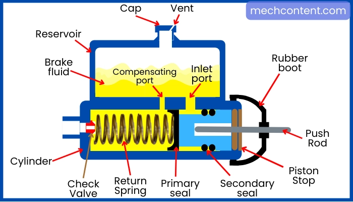
1] Reservoir: The reservoir is used to hold the brake fluid. It has a filler cap with an air vent and has two ports at the bottom.
A larger port among them is known as an intake port which feeds the oil into the compression chamber (cylinder) and a smaller port is known as a compensating port that helps to receive the excessive oil from the cylinder into the reservoir.
2] Cylinder: The cylinder along with the piston helps to raise the pressure of brake fluid, thus it is also known as pressurizing chamber. The cylinder is mounted underneath the reservoir and connected to each other with the intake port and the compensating port.
3] Piston: The piston helps to build pressure on a brake fluid inside of the cylinder. The piston is mounted inside the cylinder along with the return spring.
4] Fluid check valve: The fluid check valve also known as the residual check valve is used to keep a certain amount of pressure inside the brake fluid line. Thus, it helps for the quick application of brakes.
Therefore, due to the fluid check valve, the brake pedal never travels longer while the application of the brake.
5] Return spring: After releasing the brake pedal or lever, the return spring helps to return the piston to its original position. It is mounted inside the cylinder before the piston.
6] Seal/Cup: The gaps between the piston and cylinder are sealed with the help of primary and secondary cups/seals. The primary seal is fitted at the Springside end of the piston and the secondary seal is fitted on the opposite side.
The gap present between the primary and secondary seal, around the piston circumference is filled with the brake oil by the inlet port. The secondary seal avoids the leakage of oil behind the piston.
7] Pushrod: The pushrod is used to actuate the piston inside a master cylinder. One end of the pushrod is connected with the piston while another end is actuated with the help of a brake lever or brake pedal.
8] Rubber boot: The rubber boots prevent the entry of dust and debris into the master cylinder assembly.
Types of brake master cylinder:
Based on the number of pistons used in the cylinder, the brake master cylinder is classified as follows:
1] Single piston brake master cylinder:
As shown in figure-C, the single-piston master cylinder is used to pressurize the single fluid line by use of a single-piston. In this arrangement, the single-piston is fitted inside the cylinder along with the return spring.
The disadvantage of using a single piston master cylinder is that any leakage in the brake fluid lines can fail the complete braking system. hence it is not preferred in cars, but it is mostly used in two-wheelers for the application of disc brakes.
2] Dual master cylinder:
Dual master cylinder also known as the tandem master cylinder is used to pressurize two separate brake fluid lines. Out of them, one brake line goes to the front wheels and another goes to the rear wheels.
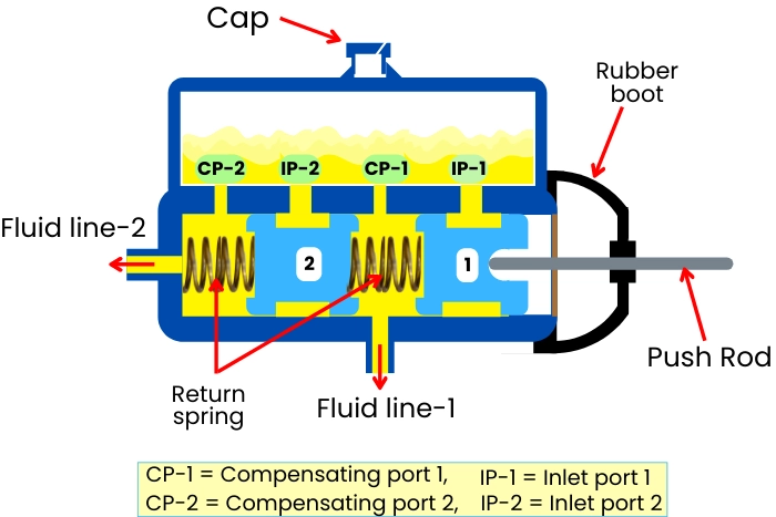
As shown in figure-D, the dual master cylinder uses two pistons mounted into the same cylinder and both are actuated by using a single pushrod.
The two pistons are separated by the return spring. The portion of the cylinder ahead of each piston acts as a separate compression chamber, and there is a separate intake port and compensation port provided for separate pistons.
Brake master cylinder working:
Here we will discuss how both single-piston master cylinder and dual-piston master cylinder works.
A] Single piston master cylinder:
Application of brake:
During the application of the brake, the pushrod moves inside to force the piston against the return spring. Initially, as the piston moves forward, the brake fluid inside the cylinder enters the fluid reservoir through the compensation port.
During the further movement of the piston, the opening of the compensating port gets covered by the primary seal. Thus it stops the return of the brake fluid in the reservoir and starts building pressure inside the cylinder/compression chamber.
When the pressure inside the cylinder exceeds the limiting pressure of the fluid check valve, the check valve becomes open, and pressurized brake fluid flows through the brake lines to actuate the wheel cylinder.
Releasing of brake:
After releasing the brake pedal, the return spring forces the piston to return to its original position. Due to the higher spring force, the piston moves suddenly to its original position. But the fluid from brake lines never returns suddenly.
Thus due to the faster return motion of the piston, the vacuum can build into the compression chamber. Due to the partial vacuum, the air bubbles can enter into the cylinder/compression chamber.
Thus to destroy this vacuum the fluid from the gap between the seals of the piston enters the cylinder through small holes in the piston and thus piston reaches the original position and uncovers the compensation port.
After reaching the piston to its original position, the brake fluid in brake lines starts to return to the cylinder. Now, this excess fluid from the brake lines returns to the reservoir through the compensation port.
B] Dual brake master cylinder:
The dual master cylinder uses two pistons within the same cylinder and each one of them pumps fluid to the separate fluid line for each pair of front wheels and rear wheels.
Normal application of brake:
Normally when the brake pedal is pressed, the push rod forces pistons 1 and 2 against the spring.
As the piston-2 covers the compensating port CP-2, the pressure starts to build in fluid line 2.
Similarly, as the piston-1 covers the compensating port CP-1, the pressure starts to build in fluid line-1.
Thus both the fluid lines get pressurized to apply the brake to the front pair and rear pair of the wheels.
Application of the brake when fluid line-2 is damaged:
In this condition when the brake pedal is pressed, the piston-2 reaches the stop of the left end, and then due to the piston-1 pressure starts to build in fluid line-1. Thus in this situation, only fluid line-1 is used for the application of the brake.
Application of the brake when fluid line-1 is damaged:
In this condition when the brake pedal is pressed, then the piston-1 touches the end of piston-2. Then the piston-1 and piston-2 move together to build pressure into the fluid line-2.
Thus in this situation, only fluid line-2 is used for the application of the brake.
The mechanism for the returning of the piston after releasing the brake is similar as a single-piston master cylinder.
FAQs:
-
What are the parts of a master cylinder?
Following are the parts of the brake master cylinder: Reservoir, piston, return spring, cylinder, check valve, inlet port, compensation port, pushrod, etc.
-
What are the four basic functions of a master cylinder?
Following are the basic functions of the brake master cylinder:
Pumps the brake fluid at high pressure
Keeps the brake lines pressurized at a certain pressure
Keeps the brake lines full of brake fluid
Stores excessive fluid into the reservoir. -
What are the two types of master cylinder?
On the basis of a number of pistons used in the cylinder, the master cylinder has the following two types:
Single piston master cylinder
Dual master cylinder (also called a Tandem master cylinder). -
Why does a master cylinder have two chambers?
The dual master cylinder has two separate chambers for separate brake fluid lines. Thus it helps to avoid the failure of braking action if any one of the brake lines gets damaged.