The crankshaft is the first rotating component in a reciprocating engine that is driven by a single or multiple reciprocating pistons.
It is also found in several applications that involve the conversion between rotating and reciprocating motion. For example, reciprocating pumps, compressors, and so on.
To know about its functions, working and how it’s made, continue reading below.
In this article, we’re going to discuss:
- What is Crankshaft?
- Crankshaft construction:
- How Crankshafts are made?
- Working of Crankshaft:
4.1. Working in IC engines:
4.2. Working in Reciprocating pumps/Compressors: - Functions of the Crankshaft:
- Crankshaft lubrication:
What is Crankshaft?
The crankshaft is the mechanical component that (along with the connecting rod) converts the reciprocating motion into rotary motion or rotary to reciprocating motion. In IC engines, the crankshaft converts the reciprocating to rotary motion. While in equipment like reciprocating compressors, and pumps, it converts rotary motion into the reciprocating motion.
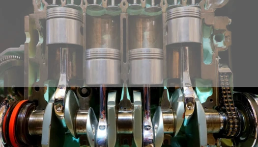
In reciprocating IC engines, the crankshaft is the largest moving component. It is located in the engine block, mounted on the main journal bearings.
The crankshaft can be of different sizes. The crankshaft used in smaller engines are of few Kgs in weight. While the crankshaft used in ships can weigh more than 100 tonnes.
As shown in the above figure, the big ends of the connecting rod are connected to the crankpins of the crankshaft.
The flywheel is connected at the one end of the main journal of the crankshaft. This flywheel attached at the end of the crankshaft smoothens the motion of the crankshaft.
The crankshaft can be driven by single or multiple pistons. The number of crankpins in the crankshaft depends on the number of pistons used in the engine. i.e. The crankshaft used for single-cylinder motorcycle engines has a single crankpin. While the crankshaft used in a 4-cylinder car engine has 4 crankpins.
The crankshaft is made using different processes: Casting, Forging, Machining, Welding, etc. It is subjected to different bending stresses and torsional stresses.
Crankshaft construction:
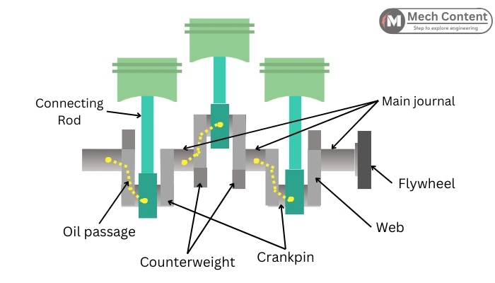
The crankshaft consists of the following parts:
1. Crank pin: It is also known as a Connecting rod journal, as it connects with the connecting rod. It is the part of the crankshaft where the big end of the connecting rod is mounted.
The motion of the connecting rod is transferred to the crankshaft at the crankpin. The crankpin surface has enough toughness to resist the shock load from the connecting rod (Shaking forces).
2. Main journals: The main journal is a central part of the crankshaft with highly polished surface. It fits into the engine block with main journal bearings. The whole crankshaft rotates around the axis of the main journal.
The surfaces of the main journals are harder than the bearing surface, as any friction that occurs between them should result in the wearing of the bearings. Thus, to keep the main journal surface intact.
For this purpose, these main journal surfaces are subjected to the surface hardening process to make them harder than the bearing surface.
3. Web: The web is the part that connects the crankpin to the main journal. The web also helps in lubrication, as the oil passage passes through the web.
4. Oil passage: The Crankshaft has oil passages to pass the lubricant from the main journal to the crankpin. The oil passage is made by drilling so that the oil from the main journal bearings is forced through the oil passage to the crankpin bearings.
5. Flywheel mounting flange: It is a provision for the mounting of the flywheel on the crankshaft.
6. Counterweight: The counterweights are attached to the web, opposite to the crankpin. The counterweight is part of the web. In the case of larger crankshafts, the counterweights are separately attached.
The role of the counterweights is to balance the centrifugal forces created by the crankpin. It also helps to balance the bending forces exerted by the piston and connecting rod.
How Crankshafts are made?
Following are the different methods through which the crankshafts are made:
1. Forging: To make the forged crankshafts, the metal billet is heated to become soft and then forged between the forging dies to take the shape of a crankshaft.
The forging process is carried out in a step-by-step manner. The forged crankshafts have a more uniform grain structure. The different internal defects in raw materials are eliminated in the forging process.
The crankshafts prepared from forging have high density and strength.
2. Welded: In this method, the crankshaft components are built separately by forging or casting and then joined together by submerged welding.
3. Casting: Casting is done by pouring the molten metal into the mold. Here the casting is used to get the basic shape of the crankshaft. It is then machined to get the actual dimensions of the crankpin and main journals.
These crankshafts are lightweight in comparison with forged crankshafts.
4. Machining: Crankshafts are also prepared by machining a raw billet of material into the final crankshaft. These crankshafts are expensive due to a lot of machining work and the cost of extra material removed during machining.
The crankshafts are of different sizes, Hence they can be prepared as a single part or as multiple components. Based on this, the crankshafts are classified as follows:
- Solid built
- Fully built
- Semi-built
Solid built: The crankshafts built as a single piece are the solid build crankshafts. The crankshafts of small-size engines are of solid build, as smaller crankshafts are easy to produce as a single part.
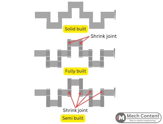
Fully built: The large-size crankshafts (crankshafts of ship engines) are difficult to build in a single piece. Thus, In this type, journals, crank pins, and webs are separately manufactured. Later, these components are assembled using Shrink fitting.
Semi-built: The semi-built crankshafts have fewer joints than the fully-built crankshafts. In semi semi-built method, the crankshaft throw (crankpin and web) is built as a single piece, and main journals are built separately. Then these components are assembled using shrink fitting.
Working of Crankshaft:
The following is the working of the crankshaft in different applications:
Working in IC engines:
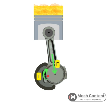
In the IC engine, the high pressure generated in the cylinder forces the piston. This force is applied to the crankpin through the connecting rod.
As the main journal of the crankshaft is fixed onto the engine block, this force creates the torque into the crankshaft, resulting in rotation of the crankshaft.
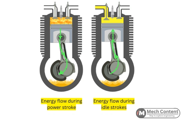
As the flywheel is connected to the crankshaft, it also starts to rotate. The high rotational inertia of the flywheel causes excessive energy to be stored during the power stroke. The energy in the flywheel is utilized by the crankshaft, during other idle strokes, to complete the remaining cycle.
In this way, the crankshaft continues its rotation.
Working in Reciprocating pumps/Compressors:
In reciprocating pumps or compressors, the purpose of the crankshaft is to convert rotary motion from an electric motor or other prime mover into the reciprocating motion used to reciprocate the piston.
The crankshafts start rotating with the starting of the motor. This causes the connecting rod to oscillate, resulting in the to-and-fro motion of the piston.
Functions of the Crankshaft:
The functions are as follows:
1] Reciprocating motion to rotating motion:
In IC engines, the piston moves with a reciprocating motion, but the vehicle requires a rotating motion to move. Thus, the crankshaft with a connecting rod helps to convert that reciprocating motion into the rotating motion.
2] Transfer power from the piston to the flywheel: This is the main function of the crankshaft to transmit power generated by the piston to rotate the flywheel.
3] Transfers power from flywheel to piston during idle strokes:
During the power (expansion) stroke, the piston is forced to move from TDC to BDC by the high-pressure combustion gases. This mechanical energy is stored in the flywheel connected to the engine.
The crankshaft continues to rotate during other strokes due to the mechanical energy stored in the flywheel. Therefore, the crankshaft helps the piston to reciprocate to perform other idle strokes (Exhaust, Suction, and Compression).
4] Balances the rotating forces: The counterweights of the crankshaft balance the rotating forces and make the power delivery smoother.
5] Uses in other machines: Other than the IC engine, the crankshaft is also used in many applications.
In reciprocating steam engines, the crankshaft is used to convert reciprocating motion into rotary motion.
In reciprocating compressors or pumps, the crankshaft converts rotary motion into the reciprocating motion to drive the reciprocating piston.
Crankshaft lubrication:
The crankshafts run at a higher RPM. Hence, the lubrication is necessary for the main journal bearings and crankpin bearings. Without lubrication, the crankshafts will wear faster due to metal-to-metal rubbing.
The bearings used in crankshaft are typically plain shell-type bearings made of softer material.
The role of lubricant in the crankshaft is to:
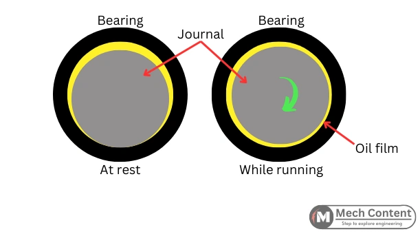
a] Create a thin film of oil around the main journal to avoid contact with the bearing surface.
b] To wipe hard abrasive particles between the gap of the shaft and bearing to avoid wear.
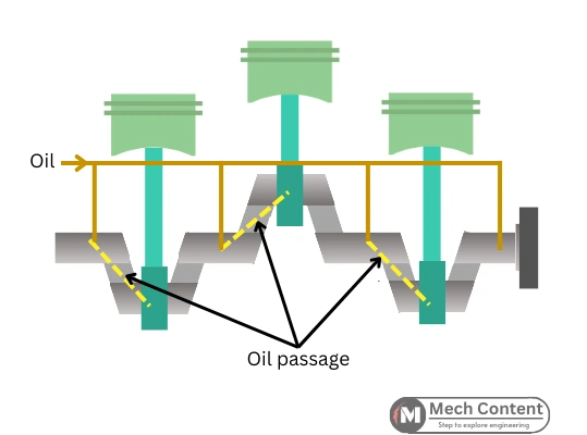
As shown above, the high-pressure oil from oil galleries is fed to the main journal through the hole on the main journal bearing. This creates a thin film of oil around the main journal to avoid the contact between the shaft and the bearings.
The oil is then passed through the oil passages made in the crankshaft to the crankpin bearings.