What is sliding mesh gearbox?
The sliding mesh gearbox is the oldest type of gearbox in which gear shifting is carried out by sliding of certain output shaft gears and meshing with certain lay shaft gears.
Thus the gears also slide while engaging and disengaging with their respective gears.
It is one of the types of manual transmission gearboxes which was used in the oldest vehicles.
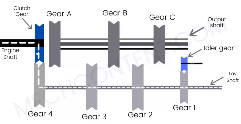
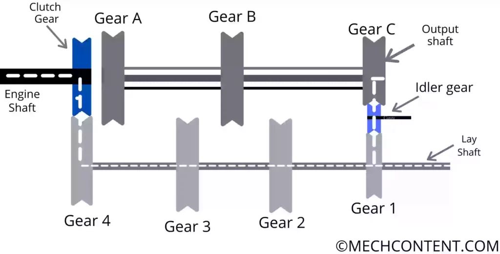
The below figure shows the simple structure of the Sliding mesh gearbox.
In this article, we’re going to discuss:
- Sliding mesh gearbox construction:
- Sliding mesh gearbox working:
- Advantages of sliding mesh gearbox:
- Sliding mesh gearbox disadvantages:
- Sliding mesh gearbox applications:
Sliding mesh gearbox construction:
It consists of the following key components:-
1) Engine Shaft: The engine Shaft has a clutch gear fixed on one end. Another end of the engine Shaft gets power from the engine.
The clutch gear is engaged with gear 4 which is mounted on a lay shaft, Therefore power transmission starts from the engine shaft to the lay shaft.
2) Lay shaft: The lay shaft has 4 fixed gears which are gear 1, gear 2, gear 3, and gear 4 (see above figure). Gear 4 meshes with the clutch gear & receives power from the engine shaft.
When the lay shaft gears mesh with output shaft gears, power transmits from the engine shaft to the output shaft through a lay shaft.
3) Output Shaft:- It is a spline shaft. It has three gears ( gear A, gear B, and gear C). These gears have internal splines hence these gears can easily slide on the output shaft and rotate with it.
The gear shifting mechanism is used in the gearbox to slide output shaft gears.
4) Clutch Gear: The clutch gear is fixed at one end of the engine shaft. Clutch gear meshes (engages) with gear 4 on the lay shaft, hence power transmits from the engine shaft to the lay shaft.
5) Fixed Gears on the lay shaft:- These four gears (gear1, gear2, gear3, gear4) are rigidly fixed on the lay shaft.
6) Gears on Output Shaft:- These gears have internal splines hence these gears can easily slide on the output shaft and rotate along with it.
7) Gear shifting mechanism: The gear shifting mechanism is used to push output shaft gears (either on the left side or right side) on the output shaft.
One end of this mechanism is connected to the gear pedal and another end is connected to output shaft gears.
Therefore, when the driver shifts the gear pedal to achieve the desired gear, through the gear shifting mechanism, gears on the output shaft slide to mesh (engage) with gears on the lay shaft.
8) Gear Pedal:- The Gear pedal is connected to gears on the output shaft through a gear shifting mechanism.
9) Idler Gear:- It is a Separate Gear used in this gearbox. The idler gear is used to achieve reverse gear.
Sliding mesh gearbox working:
In a sliding mesh Gearbox, when the driver presses the gear pedal, the Gear slides (moves) on the output shaft and meshes with its respective gears on the lay shaft. Therefore in such a way when gear meshes, speed/torque is obtained at the output shaft.
In a Neutral position, output shaft gears do not mesh with gears on the lay shaft hence power only transmits from the engine shaft to the lay shaft.
Below are four gear positions we can obtain in this gearbox/transmission:-
First Gear:-
It is achieved when Gear C moves towards the left side and Meshes with a small Gear 2. Hence small gear 2, transmits power to gear C.
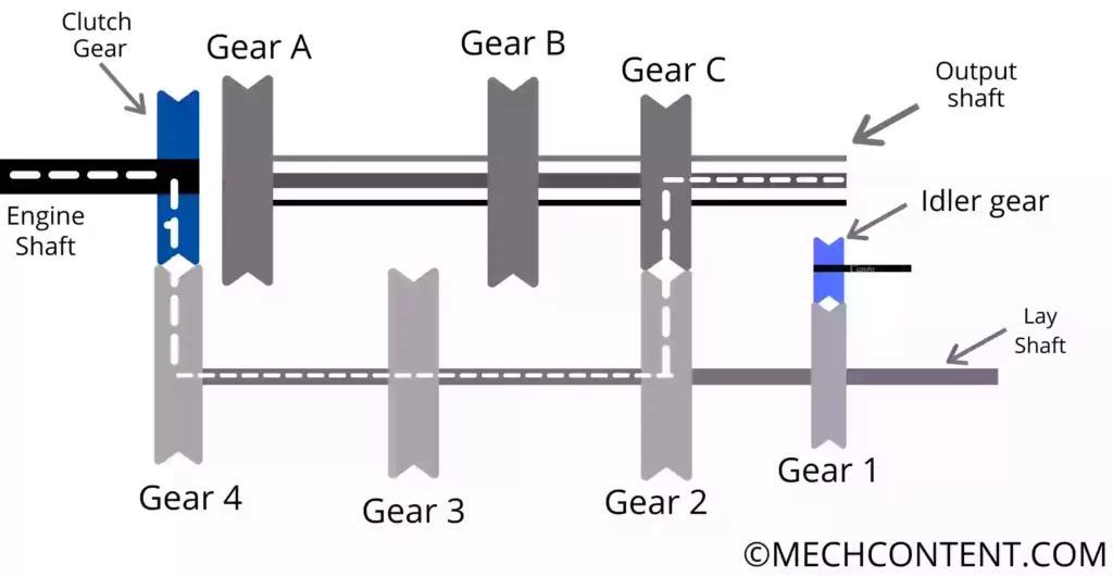
In the first gear, high torque and low speed are obtained at the output shaft.
Power Transmission= Engine Shaft -> Clutch Gear -> Gear 4-> lay shaft -> Gear 2 -> Gear C -> Output Shaft
Second Gear:-
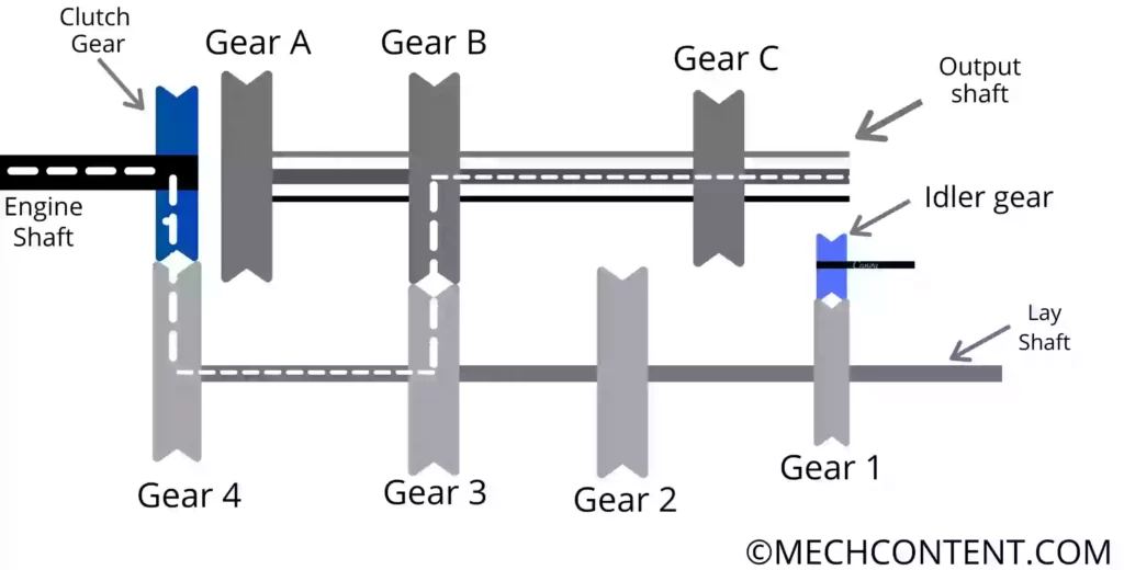
It is achieved when gear B moves towards the left side and meshes with gear 3. Hence gear 3 transmits power to gear B. In the second gear, medium torque and speed are obtained at the output shaft.
Power Transmission= Engine Shaft -> Clutch Gear -> Gear 4 -> lay shaft -> Gear 3 -> Gear B -> Output Shaft
Third gear:-
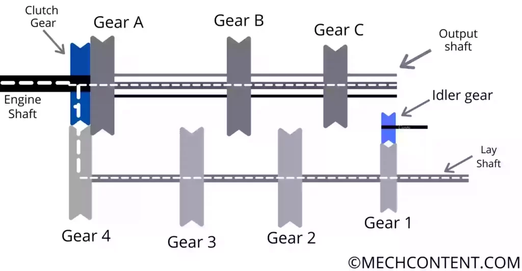
It is achieved when gear A directly coupled with the clutch gear. Hence power transmits from the clutch gear to the output shaft.
In the third gear, high speed and low torque are obtained at the output shaft. In the third gear, both shafts (Engine shaft and Output Shaft) rotate at the same speed.
Power Transmission= Engine Shaft -> Clutch Gear -> Gear A -> Output Shaft
Reverse Gear:-
It is achieved when gear C moves towards the right side & meshes with idler gear. Hence power transmits from gear 1 to gear C through Idler gear.
When the gear on the lay shaft directly meshes (engages) with gears on the output shaft, the output shaft rotates in the opposite direction of the lay shaft. In this case, the vehicle moves in the forward direction.
Hence to achieve reverse direction, the output shaft should rotate in the same direction as that of the lay shaft.
If the idler gear is used between the lay shaft gear 1 and output shaft gear C, the output shaft will rotate in the same direction as that of the lay shaft. Here we get the reverse gear to move the vehicle in the reverse direction.
Power Transmission= Engine Shaft -> Clutch Gear -> Gear 4 -> lay shaft -> Gear 1 -> Idler Gear -> Gear C -> Output Shaft
Advantages of sliding mesh gearbox:
A sliding mesh gearbox has the following advantages:
- It is easy to manufacture.
- It has more efficiency as compared to a constant mesh gearbox since only one gear is in meshing.
Sliding mesh gearbox disadvantages:
A sliding mesh gearbox has the following disadvantages:
- It has a high tear and wear since more friction occurs.
- It requires more effort for the engagement of gears.
- It is large in size as compared to a constant mesh gearbox.
Sliding mesh gearbox applications:
The sliding mesh gearbox is the old type of gearbox that has applications in the oldest types of vehicles as follows:
- In Mercedes 35 HP
- In Fiat 6 HP
- In Alpha 12 HP.
FAQs:
-
What gear is used in sliding mesh gearbox?
The spur-type gears are used in the sliding mesh gearbox.
-
What is the difference between sliding mesh and constant mesh gearbox?
In the sliding mesh gearbox, only one gear is meshing but in the constant mesh gearbox, all gears are constantly meshing.
-
In what way a constant mesh gearbox is better than a sliding mesh gearbox?
In the sliding mesh gearbox, the chances of gear teeth failures are higher because of the continuous engagement of gears while in the case of a constant mesh gearbox, the dog clutch gets damaged not the gears since gears are engaged by the dog clutch.