Synchromesh gearbox is the latest type of manual transmission gearbox. Let’s discuss its working principle, construction, working, advantages, etc.
In this article, we’re going to discuss:
- What is synchromesh gearbox?
- Construction:
- Working principle:
- Working of synchromesh gearbox:
- Advantages and disadvantages of synchromesh gearbox:
- Application of synchromesh gearbox:
What is synchromesh gearbox?
Synchromesh gearbox uses a synchronizer ring and hub to engage output gears with the output shaft. In this gearbox, the lay shaft gears constantly meshes with the output shaft gears, as like a constant mesh gearbox.
The output gears freely rotate over the output shaft. Thus, to engage the output shaft with the output gears of required gear ratio (gear-A/gear-B/gear-C/gear-D), this gearbox uses synchronizer ring and synchronizer hub.
The purpose of using synchronizer ring and synchronizer hub is similar to the dog clutch in constant mesh gearbox.
The purpose of synchronizer ring in this gearbox is to bring the speed of output shaft equal to the speed of output gear that helps to smoothly engage gears.
This gearbox arrangement was invented in 1918 by Earl Thompson.
Construction:
It consists of the following key components:
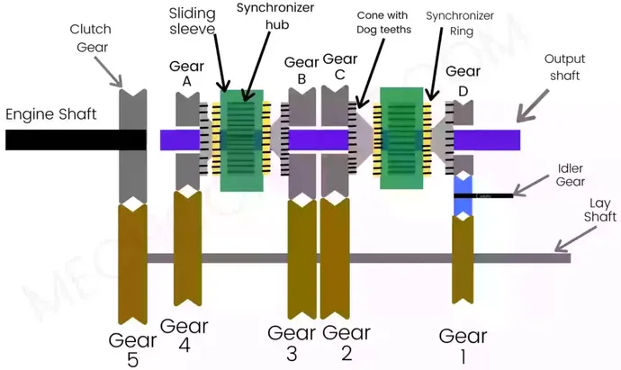
1) Engine Shaft: One end of the engine shaft is connected to the clutch. When the clutch engages, the engine shaft starts rotating at the speed of the engine.
On the other end of the engine shaft, the clutch gear is fixed. The clutch gear constantly meshes with the lay shaft gear. Hence, the engine shaft transmits power transmission to the lay shaft.
2) Lay Shaft: There are 5 fixed gears located on the lay shaft are gear1, gear2, gear3, gear4, gear5.
The Gear 5 is located on lay shaft meshes with clutch gear which rotates with power received from the engine shaft.
Another four gears fixed on the lay shaft are constantly meshing with the gears on the output shaft.
Hence, power transmission occurs from the engine shaft to the gears on output shaft gears through the gears on lay shaft.
3) Output Shaft: There are 4 Gears on the output shaft that freely rotates over the shaft.
These gears have cones attached to it. Cones have Dog teeth for the Gear engagements.
When the driver shifts the gear, through the shift fork, sliding sleeve press the synchronizer ring on the cone.
4) Cone: It is an external cone shape part that is attached to the output gears. Cones have dog teeth for the engagement.
By moving the shift fork, the sliding sleeve (having internal teeth) slides and internally meshes with the dog teeth of the cone.
5) Synchronizer Hub: Synchronizer hub is fixed on the output shaft. It has external teeth for the sliding of the sleeve.
6) Sliding Sleeve: Sliding Sleeve has internal teeth and meshes internally with the teeth on Synchronizer Hub. The sliding sleeve can easily slide over the synchronizer hub.
Its purpose is to interlock Synchronizer Hub on output shaft and cone on output gears.
The sliding sleeve is operated manually using the shift fork and gear lever. Hence, when the driver shifts the gear, the shift fork moves the sleeve on the hub.
7) Synchronizer Ring: Synchronizer Ring has an internal cone shape to engage with the cone.
When the driver shifts the gear, the shift fork moves the sleeve, therefore the sleeve presses the Synchronizer Ring inside the cone.
Working principle:
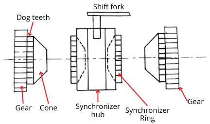
As shown in the above figure, the cones are attached to the gears, and it has dog teeth for the gear engagements.
While, the synchronizer ring has internal cone shape to engage with the cone.
Sliding Sleeve is internally meshing with the Synchronizer hub. Hence, the sliding sleeve can slide easily in both directions.
When the driver shifts the gear, the shift fork moves the sleeve, therefore the sleeve presses the synchronizer ring over the cone.
Hence, due to friction between the cone and synchronizer ring, the output shaft starts rotating with the gear at the same speed.
The Synchronizer ring helps to bring the speed of output shaft and speed of output gear to the same.
Then sleeve engages on the dog teeth of cone, hence in such way with the help of synchronizer devices smooth engagement is done.
Working of synchromesh gearbox:
In the synchromesh gearbox, gear shifting is done manually with the help of a shift fork.
When the driver shifts the gear, the shift fork moves the sleeve on the hub. A sliding sleeve helps in the engagement of gears by internally locks the cone & hub by internally meshing.
In a Neutral Position, the sliding sleeve is at the middle of the hub. let’s see, how it works to obtain different gear steps.
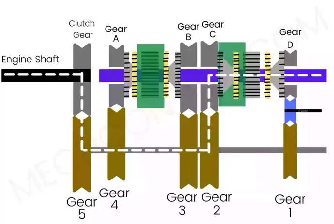
First Gear:
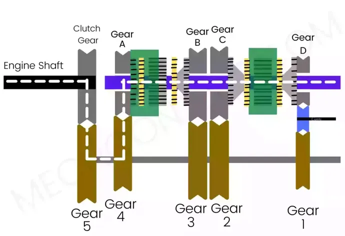
The left sliding sleeve moves towards the left and press its synchronizer ring over the cone of Gear-A. Then the sleeve internally meshes with the cone of gear-A and hub and locks them.
Hence, the output shaft starts to rotate at a speed of gear A.
Therefore, in first gear, the power transmits from:
Engine shaft → Clutch gear → gear 5 → lay shaft → gear 4 → gear A → output shaft
Second Gear:
In this case, the left sliding sleeve slides towards the right and press the synchronizer ring over the cone of gear-B. Then, the sleeve internally meshes with the cone of gear-B and hub and locks them.
Hence, the output shaft starts to rotate at a speed of gear B.
In second gear, the power transmits from:
Engine shaft → Clutch gear → gear 5 → lay shaft → gear 3 → gear B → output shaft
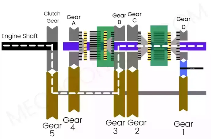
Third Gear:
In this case, the right sliding sleeve moves towards the left and press the synchronizer ring over the cone of gear-C. Then the sleeve internally meshes with the cone of gear-C and hub and interlock them.
Hence, the output shaft starts to rotate at a speed of gear C.
In third gear, the power transmits from:
Engine shaft → Clutch gear → gear 5 → lay shaft → gear 2 → gear C → output shaft
Reverse Gear:
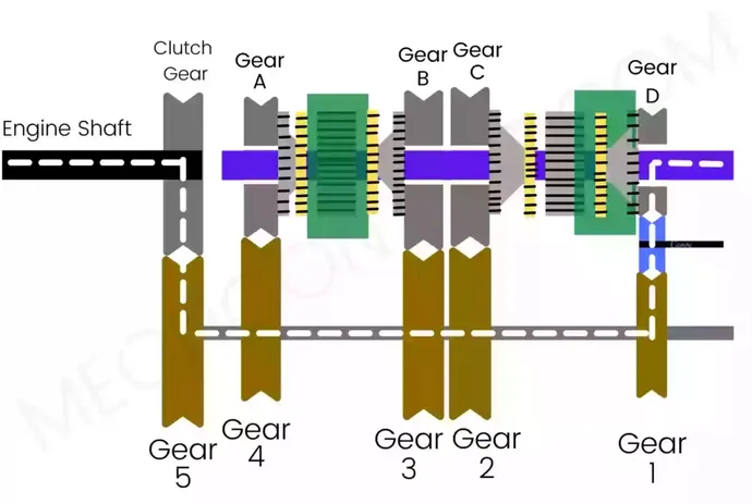
The right sliding sleeve moves towards the right and press the synchronizer ring over the cone of gear-D. Then the sleeve internally meshes with the cone of gear-D and hub and interlocks them.
Hence, the output shaft starts to rotate at a speed of gear D
In reverse gear, the power transmits from:
Engine shaft → Clutch gear → gear 5 → lay shaft → gear 1 → Idler gear → gear D → output shaft
Advantages and disadvantages of synchromesh gearbox:
The advantages of this gearbox are as follows:
- It provides smooth & quite shifting of gears due to use of Synchronizer Ring and Sliding sleeve.
- No need of skill to operate.
- It has more power transmission capacity as compared to constant mesh gearbox.
- No double declutching is required.
The disadvantages of this gearbox are as follows:
- It is a bulky gearbox.
- It is Expensive.
- It requires more space.
Application of synchromesh gearbox:
This kind of gearbox is found in following applications:
- Sports Car
- Local Deliveries Trucks
- Wagon R Vxi
You may like to read:
- Read here: Sliding mesh gearbox