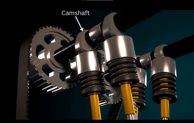
In four-stroke engines, the camshaft is responsible for the timely operation of the valves, helping to perform different processes during the engine cycle. It is driven by the engine crankshaft and sits on top of the engine. The size and number of cams on the camshaft can vary depending on the engine size and the number of cylinders present.
Continue reading to learn about its functions, construction, types, workings, and much more.
Contents:
What is Camshaft?
The camshaft is a cylindrical shaft with cams that controls the opening of intake and exhaust valves of the engine.
The intake cams on the camshaft control the intake valves while the exhaust cams control the exhaust valves.
The camshaft is located at the top of the IC engine inside the cylinder head. Other than cams, the camshaft also has bearing journals to support the camshaft.
Some engines have both intake and exhaust cams on the same shaft. The SOHC (Single overhead camshaft) engine uses a single camshaft per cylinder bank. While some engines have intake cams on separate shafts and exhaust cams on separate shafts. DOHC (Double overhead camshaft) engines use a two camshaft per cylinder bank.
Therefore, engines can run on single or multiple camshafts. The V-engines with DOHC have 4 camshafts i.e. Two camshafts for each cylinder bank.
Parts:
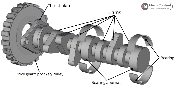
The Camshaft in the Internal combustion engine consists of the following main parts:-
A] Cam:
Cam rotates to actuate the tappet of the valves. The eccentric profile of the cam opens and closes the valve for the right duration. The shape of the cam varies based on the Opening duration, Type of tappet used (Flat/Roller).
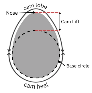
The cam profile consists of following regions:
The surface of the cam that comes in contact with the tappet (follower) can be divided as cam heel and cam lobe portions.
Cam heel: While working when the tappet (follower) is moving over the cam heel portion, the tappet has no vertical movement. The cam heel is the portion of the cam where the tappet has no lift. Hence the valve remains closed.
Cam lobe: Cam lobe is responsible for opening and closing of the valves. When the tappet is passing over the cam lobe surface, it moves in a vertical direction. This causes opening and closing movement of the valve.
Base circle: It is the circle that can be drawn from the centre of the cam that touches the cam heel surface.
Cam lift: It is equivalent to the vertical distance travelled by the tappet (follower). It is also called a lobe lift, a height of cam lobe from its base circle.
Nose: It is the point on the cam profile at the maximum lift.
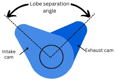
Lobe separation angle: The relative positions of the intake and exhaust cams are stated in terms of lobe separation angle. It gives the angle between centerlines of the intake cam lobe and exhaust cam lobes of the same cylinder.
B] Camshaft Bearing journal:
This part of the camshaft sits into the camshaft bearing. The camshaft is supported at the bearing journal.
C] Shaft:
All the cams and cam bearing journals are mounted on the shaft. It possesses higher torsional rigidity, as the twisting of the camshaft can affect the valve timing.
D] Camshaft bearings:
The role of the camshaft bearing is to support the camshaft. In the case of a multi-cylinder engine, the camshaft uses a number of bearings at different locations to bear the dynamic loadings.
E] Drive gear/Sprocket:
One of the ends of the camshaft has provision for the mounting of the Driving gear or Sprocket. It is driven by the crankshaft through chain/belt/gear drive.
F] Thrust plate:
The Purpose of the thrust plate is to stop the axial (horizontal) movement of the camshaft. The thrust force arises due to the interaction between the cam lobes and the tappets. This force acts in the axial direction of the camshaft. This causes movement of the camshaft in axial direction.
The thrust plate is mounted on the camshaft before timing gear and fitted on the engine block. This plate holds the camshaft on the engine block.
How does the Camshaft operate Valves?
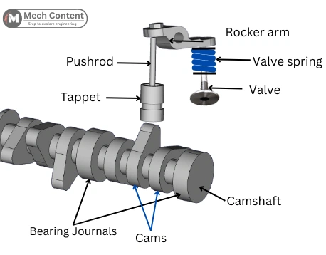
The camshaft is driven by the crankshaft through a timing belt or timing chain. As shown in the above figure, the cams on the camshaft are structured in such a way that it operates the valves of each cylinder at the right time and for the right duration.
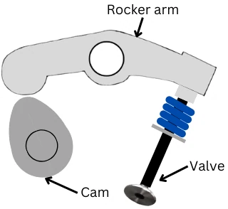
A cam actuates the tappet (follower). The tappet is further connected with the pushrod, rocker arm to operate the valve.
When the tappet passes over the cam heel surface, the tappet never moves in a vertical direction and the valve remains in closed condition. When the tappet passes over the cam lobe surface, the tappet moves in vertical direction, thus causing the valves to open and close.
Camshaft functions:
Camshaft performs following important functions in an engine:-
1) Controls the valve opening: The main role of the camshaft is to open and close the intake and exhaust valves at the right time.
2] Open valves on exact time: In multi-cylinder engines, a single camshaft actuates the valves of multiple cylinders on exact time. It is due to the valve timing mechanism (timing chain, timing belt) and precise position of the cam lobes over the camshaft.
The all cams are precisely made over the camshaft, this ensures the opening of the valves on exact time relative to each other.
3] Open valves for exact duration: The lobe profile of the camshaft decides the valve opening duration (in terms of crankshaft angle). Thus every time the valve opens for the exact duration.
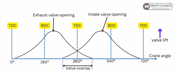
4] Valve overlap: Valve overlap is the situation when the exhaust and intake valves remain open at same time. This facilitates the process of Scavenging.
It occurs a few degrees before the end of the exhaust stroke and a few degrees after starting the suction stroke.
The overlap between the intake and exhaust valves is due to the overlapping of the intake and exhaust lobes on the camshaft.
In single overhead camshaft, as the position of intake and exhaust cams is fixed, therefore in these camshafts the valve overlap is fixed. While In dual overhead camshaft as intake and exhaust valves are operated by separate cams. Thus in this system, the overlap between intake and exhaust valves can be adjusted.
Types of Camshaft:
The camshafts are classified on different basis as follows:-
A] Based on Number of Camshaft per cylinder bank:
1. Single overhead camshaft (SOHC): This system uses a single camshaft for controlling the intake and exhaust valves.
Here, the camshaft is mostly placed in the middle of the intake and exhaust valves. Hence this system necessarily requires rocker arms for the actuation of valves.
2. Double overhead camshaft (DOHC): This system uses two separate camshafts for controlling intake and exhaust valves. The variable valve timing is possible with the DOHC system.
The other advantage of using DOHC is that it doesn’t require a rocker arm as the cams are mounted above the valves.
But this system takes more space in the engine head as compared to SOHC due to the extra camshaft. Thus it makes engines more bulky.
B] Based on type of tappet used:
1. Flat tappet camshaft: These camshaft are designed to actuate a flat tappet. The flat tappet is subjected to more friction in comparison with roller tappets. See below figure that indicates the difference between the cam profiles in flat and roller tappet camshafts.
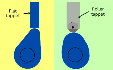
2. Roller tappet camshaft: These camshafts are designed for actuating roller tappet. The roller tappet has a bearing or roller that contacts the cam surface.
The cam lobes designed for the roller tappet have a more rounded profile at the maximum lift (see above diagram). Thus on the roller cam surface, the tappet stays at maximum lift position for longer duration. Therefore in the roller tappet camshaft, the valves remain fully open state (at maximum lift) for a longer time.
C] Based on Number of Cylinders:
The size of the camshaft also varies based on the number of cylinders used in the cylinder bank. i.e. Single, Two, or even Six-cylinder camshaft.
Three types of Camshaft drive mechanism:
The camshaft is run by the crankshaft at half of the speed of the crankshaft.
It is necessary that the camshaft should operate in such a way that the intake and exhaust valve open and close at the right time. It means that the valve should open and close based on the position of the piston during the combustion cycle.
The coordination between position of piston and valve opening is achieved by one of the following three drives.
a) Timing Belt: It has a toothed belt that runs over toothed pulleys mounted on camshaft and crankshaft.
b) Timing Chain: This mechanism uses a chain drive that runs over the sprockets mounted on the camshaft and crankshaft.
c) Timing gear: This mechanism uses gears to connect the crankshaft and camshafts.
It is necessary that no slip occurs in any of the above driving mechanisms, to avoid disturbing the valve timing.
Manufacturing methods:
Following are some of the different methods used to produce camshafts:-
1] Casting: This method is used for casting camshafts from alloys of cast iron. Further these camshafts undergo machining and heat treatment.
2] Forging: Camshafts are also prepared by cold forging or by hot forging. In this method a material blank is compressed into the forging die to get a rough formed camshaft. It is then machined to get the final dimensions.
3] Machining: In this method, the camshafts are prepared from metal billet only by machining process. The excessive material from the metal billet is removed by machining to take the final shape of the camshaft.
Heat treatment:
After machining, the camshafts undergo a heat treating (surface hardening) process. The cam surface wears due to the friction between the cam surface and tappet. This reduces the life of the camshafts. Thus to increase wear resistance of the cam surface, the surface hardening is performed for camshafts. Induction hardening, Nitriding are the methods used for surface hardening of the camshafts.