We are aware that when we twist an eraser or a spring, they change shape. In this instance, the deformation is referred to as a shear deformation, and the term used to express how much shear deformation has occurred is known as shear strain. In this article, we are discussing in detail about the shear strain.
In this article, we’re going to discuss:
- What is a Shear Strain?
- Shear strain equation:
- Sign convention:
- Solved numericals on shear strain:
- FAQs:
What is a Shear Strain?
Shear strain is the measure of shear deformation caused due to shear stress. It indicates the change in the shape of the object and it is denoted by the symbol `\gamma`.
In simple words, the shear strain is the change in angle between two line elements of the object corners due to the shear stress.
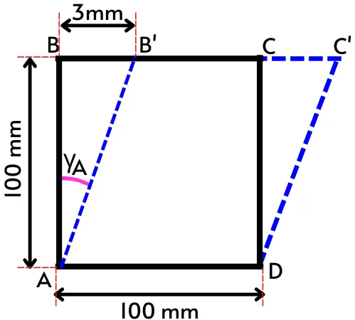
The shear strain causes due to the application of the shear force. The object shown in the below figure is under shear stress because of the application of equal and opposite shear forces at the opposite faces of the object.
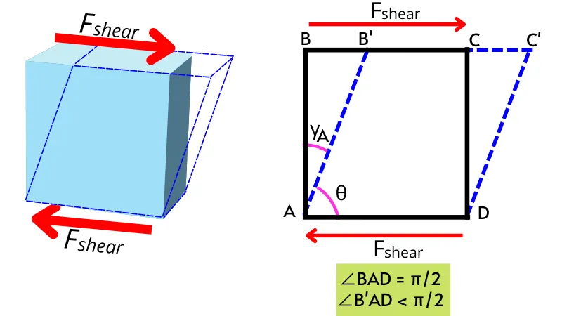
As shown in the figure, after the application of shear forces point B gets displaced to the new position B’ and point C is displaced to C’. Therefore the angle at corner A gets reduced from the right angle (`\angleBAD`) to the acute angle (`\angleB’AD`).
Thus for corner A in the above figure, the shear strain is given by,
Shear strain = Initial angle at ‘A’ – Final angle at ‘A’
`\text{Shear strain}=\angle BAD\ – \angleB’AD`
`\text{Shear strain}=\frac{\pi}{2}-\theta=\gamma_{A}`
Thus the term `\gamma_{A}` in the above figure indicates the shear strain at corner A.
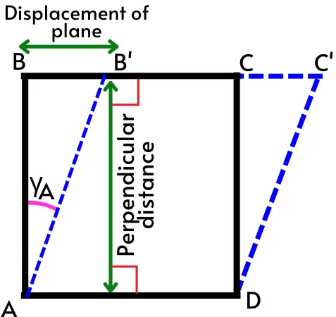
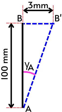
For the triangle ABB’ in the above figure, by using the simple trigonometric equation, we can write,
`tan(\gamma_{A})= \frac{BB’}{AB}`
`\therefore \gamma_{A} = tan^{-1}(\frac{BB’}{AB})`
This is the equation to find the shear strain at corner-A.
Where,
`\gamma_{A}` = Shear strain at corner A
BB’ = displacement of the plane in direction of shear force
AB = Perpendicular distance of the displaced plane from the opposite plane
For the smaller value of `\gamma`, we can write,
`tan(\gamma_{A}) \approx \gamma_{A}`
`\therefore\gamma_{A} = \frac{BB’}{AB}`
Thus the shear strain is also given by the ratio of the amount of shear deformation in the object to the perpendicular distance from the opposite plane.
Up to the proportionality limit of the material, the shear strain can also be calculated by using Hooke’s law as follows,
`\text{Shear strain}(\gamma) = \frac{\text{Shear stress}(\sigma)}{G}`
Where, G = Modulus of rigidity
The shear strain is a unitless quantity and it is expressed in terms of radians.
Shear strain equation:
For the object shown in the above figure, the shear strain at any corner is given by,
`\gamma = tan^{-1}(\frac{\text{displacement of plane in direction of shear force}}{\text{perpendicular distance from opposite plane}})`
The smaller shear strain can be given by,
`\gamma = \frac{\text{displacement of plane in direction of shear force}}{\text{perpendicular distance from opposite plane}}`
By using Hooke’s law, the shear strain is given by,
`\text{Shear strain} (\gamma) = \frac{\text{Shear stress} (\sigma)}{\text{Modulus of rigidity}(G)}`
Sign convention:
The sign convention used for the shear strain is as follows,
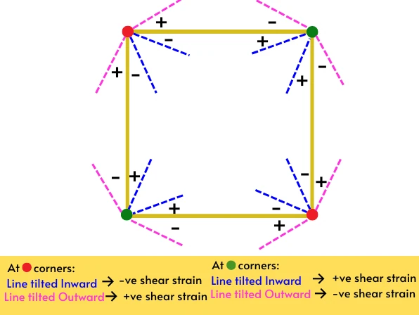
For the top-left and bottom-right corners (🔴),
- The shear strain is positive if, the line elements at the corners are tilted outward.
- The shear strain is negative if, the line elements at the corners are tilted inward.
For the top-right and bottom-left corners (🟢),
- The shear strain is positive if, the line elements are tilted inward.
- The shear strain is negative if, the line elements are tilted outward.
See the below example to understand the sign convention clearly.
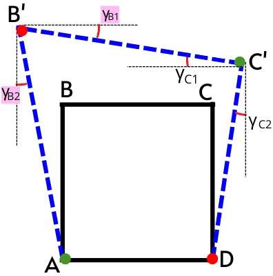
At corner B’:-
The corner B’ experiences two shear strains `\gamma_{B1}` and `\gamma_{B2}` due to line element B’C’ and AB’ respectively.
As we have discussed above at the top-left and bottom-right corners, the shear strain is positive if, the line elements at the corners are tilted outward and negative if the line elements are tilted inward.
At corner B’ the line B’C’ is tilted inward hence its respective shear angle `\gamma_{B1}` is negative. While line AB’ at corner B’ is also tilted inward so the shear angle `\gamma_{B2}` also becomes negative.
Thus the total shear angle at the corner B’ can be found by taking the sum of both shear angles.
`\therefore \gamma_{B’} = -\gamma_{B1} – \gamma_{B2}`
At corner C’:-
The corner C in the above figure is also experiencing two shear angles i.e. `\gamma_{C1}`, and `\gamma_{C2}`.
As per the above discussion, for the top-right and bottom-left corners, the shear strain is positive if, the line elements are tilted inward and negative if line elements are tilted outward.
Line C’D at corner C’ is tilted inward, thus its respective shear angle `\gamma_{C2}` is positive while the line B’C’ at corner C’ is tilted outward hence its respective shear angle `\gamma_{C1}` is negative.
Thus the total shear angle at the corner C’ is given by,
`\therefore \gamma_{C’} = -\gamma_{C1} + \gamma_{C2}`
Solved numericals on shear strain:
1] For the component shown in the figure, find the shear strain at corner A.
Solution:-
Corner A shown in the above figure is the bottom left corner.
Thus as per the above sign convention, at the bottom left corner, if the line is tilted inward then the shear strain is considered positive and if tilted outward then the shear strain is negative.
As the line AB’ at corner A is tilted inward then the shear strain `\gamma_{A}` is considered as positive.
From the above figure, the shear strain at corner A is given by,
`\gamma_{A} = tan^{-1}(\frac{BB’}{AB})`
`\gamma_{A} = tan^{-1}(\frac{3}{100})`
`\mathbf{\gamma_{A}=0.029\ \text{radian}}`
2] For the deformation shown in the figure below, find the shear strain at corners A and B.
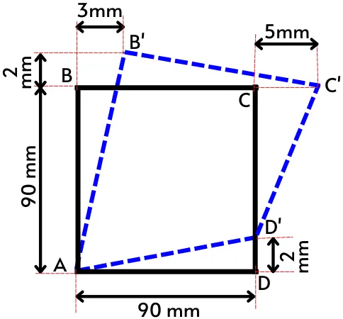
Solution:-
A] Shear strain at corner A:
As shown in the above figure, corner A experiences shear strain at both lines AB and AD i.e. `\gamma_{A1}` and `\gamma_{A2}`.
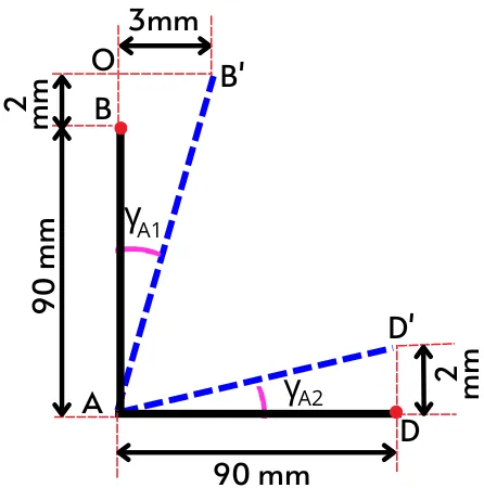
From the above figure, the shear strain `gamma_{A1}` is given by,
`\gamma_{A1} = tan^{-1}(\frac{OB’}{AO})`
`\gamma_{A1} = tan^{-1}(\frac{3}{90+2})`
`\gamma_{A1}=0.0325\ \text{radian}`
And the `gamma_{A2}` is given by,
`\gamma_{A2} = tan^{-1}(\frac{DD’}{AD})`
`\gamma_{A2} = tan^{-1}(\frac{2}{90})`
`\gamma_{A2}=0.0222\ \text{radian}`
As per the sign convention, at the bottom left corner, the shear strain is positive if the line is tilted inward and negative if the line is tilted outward.
As both the lines AB’ and AD’ are tilted inward therefore the `\gamma_{A1}` and `\gamma_{A2}` are positive.
Thus the total shear strain at corner A is given by the sum of shear strain `\gamma_{A1}` and `\gamma_{A2}`.
`\therefore \gamma_{A} = \gamma_{A1} + \gamma_{A2}`
`\gamma_{A}` = 0.0325 + 0.0222
`\mathbf{\gamma_{A}=0.0547\ \text{radian}}`
B] Shear strain at corner B’:
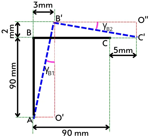
As shown in the above figure, corner B’ also experiences shear strain at line AB and line BC i.e. `\gamma_{B1}` and `\gamma_{B2}`.
From the above figure, the shear strain `\gamma_{B1}` is given by,
`\gamma_{B1} = tan^{-1}(\frac{AO’}{B’O’})`
`\gamma_{B1} = tan^{-1}(\frac{3}{90+2})`
`\gamma_{B1}=0.0325\ \text{radian}`
The shear strain `\gamma_{B2}` is given by,
`\gamma_{B2} = tan^{-1}(\frac{O’’C’}{B’O’’})`
`\gamma_{B2} = tan^{-1}(\frac{2}{90-3+5})`
`\gamma_{B2}=0.0217\ \text{radian}`
As per the sign convention, at the upper left corner, the shear strain is positive if the line is tilted outward and negative if the line is tilted inward.
In the above figure, line AB’ at corner B’ is tilted outward, therefore `\gamma_{B1}` is positive. While line B’C’ is tilted inward, hence shear strain `\gamma_{B2}` is negative.
Thus the total shear strain at corner B’ is given by,
`\gamma_{B’}=\gamma_{B1}+(-\gamma_{B2})`
`\gamma_{B’}=0.0325\ –0.0217`
`\mathbf{\gamma_{B’}=0.0108\ \text{radian}}`
FAQs:
-
Why is shear strain significant?
The shear strain gives the measure of shear deformation caused by the shear stress.
-
When is a body under shear strain?
When the body is subjected to the shear forces, it experiences the shear strain.
-
What distinguishes the shear strain from the direct strain?
The shear strain indicates a change in the shape of the object while the direct strain indicates a change in the length of the object.
-
When does shear strain become negative?
At the top-right and bottom-left corners, the shear strain is negative when the angle between two lines increases. At the top-left and bottom-right corners, the shear strain is negative when the angle between the lines decreases.
informative