Contents:
What is the Stirling cycle?
The Stirling cycle is a thermodynamic cycle that consists of two isothermal processes and two isochoric processes. It is patented in 1816 by Robert sterling.
It is slightly different than the Carnot cycle. The Stirling cycle replaces the isentropic processes in the Carnot cycle with the isochoric processes. This cycle has the same maximum efficiency as that of the ideal Carnot cycle.
The Stirling cycle can function as a heat pump by operating in the opposite direction as it is reversible.
It uses the same working fluid repeatedly, thus the Stirling cycle behaves like a closed system.
Stirling cycle PV and TS diagram:
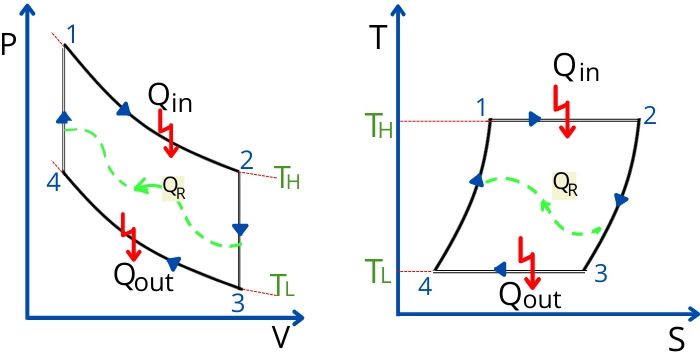
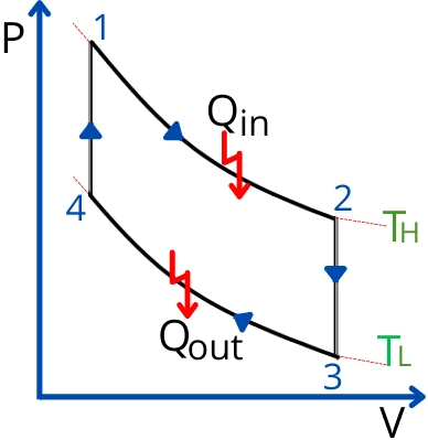
The ideal Stirling cycle consists of the following 4 processes.
- Process 1-2:- Isothermal heat addition/Isothermal expansion
- Process 2-3:- Constant volume heat rejection
- Process 3-4:- Isothermal heat rejection/Isothermal compression
- Process 4-1:- Constant volume heat addition
In the above figure, the `Q_{R}` indicates the heat transfer because of the regeneration.
Stirling cycle process:
The Stirling cycle consists of two isothermal and two isochoric processes. Each of the processes is described below:-
1] Isothermal heat addition:-
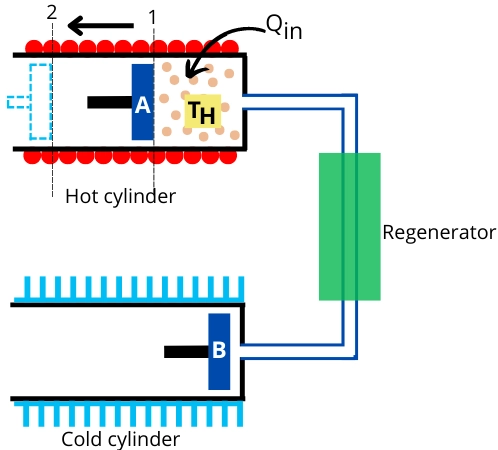
The unit shown in the above figure will help to understand the different processes that occur in the Stirling cycle. It consists of a hot cylinder at temperature `T_{H}`, a cold cylinder at temperature `T_{L}`, and a regenerator.
The process shown in the above figure indicates isothermal heat addition. In this process, the air present in a hot cylinder is heated by an external heat source. During this heat addition, piston-A moves toward the left to cause isothermal expansion of air.
2] Constant volume heat removal:-
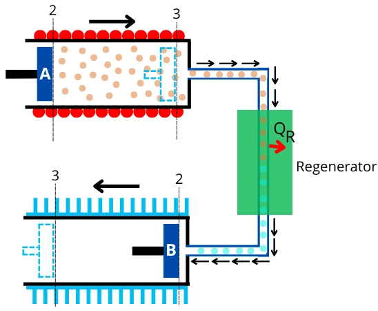
During this process, the air in the hot cylinder is transferred to the cold cylinder through the regenerator. For this purpose, piston-A moves to the right while piston-B moves to the left.
In the regenerator, air rejects the heat to change its temperature from `T_{H}` to `T_{L}`, and then it enters into the cold cylinder.
3] Isothermal heat rejection/Isothermal compression:-
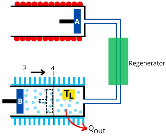
In this process, the air inside the cold cylinder undergoes isothermal compression with rejecting heat to the external sink. During this process, the piston-B moves inward.
4] Constant volume heat addition:-
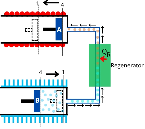
During this process, the air inside the cold cylinder is transferred to the hot cylinder through the regenerator.
For this purpose, piston-B moves inward while piston-A moves outward. While passing through the regenerator, the air takes heat `Q_{R}` from the regenerator to raise its temperature from `T_{L}` to `T_{H}`.
Stirling cycle efficiency derivation:
The amount of heat added during the process 1-2 is given by,
`Q_{\text{in}}=Q_{12}=P_{1}v_{1}ln(\frac{v_{2}}{v_{1}})`
`Q_{\text{in}}=RT_{1}ln(\frac{v_{2}}{v_{1}})\cdots[\becauseP_{1}v_{1}=RT_{1}]`
`Q_{\text{in}}=RT_{H}ln(\frac{v_{2}}{v_{1}})\cdots[\becauseT_{1}=T_{H}]`
The amount of heat rejected during isothermal process 3-4 is given by,
`Q_{\text{out}}=Q_{34}=P_{3}v_{3}ln(\frac{v_{4}}{v_{3}})`
`Q_{\text{out}}=RT_{3}ln(\frac{v_{4}}{v_{3}})\cdots[\becauseP_{3}v_{3}=RT_{3}]`
`Q_{\text{out}}=RT_{L}ln(\frac{v_{4}}{v_{3}})\cdots[\becauseT_{3}=T_{L}]`
The net work done by the cycle is given by,
`W_{\text{net}}=Q_{\text{net}}`
`W_\text{net} = Q_{\text{in}} + Q_{\text{out}}`
`W_\text{net} = RT_{H}ln(\frac{v_{2}}{v_{1}})+RT_{L}ln(\frac{v_{4}}{v_{3}})`
`W_\text{net} = RT_{H}ln(\frac{v_{2}}{v_{1}})-RT_{L}ln(\frac{v_{3}}{v_{4}})`
Now the thermal efficiency of the Stirling cycle is given by,
`\eta_{\text{th}} = \frac{W_{\text{net}}}{Q_{\text{in}}}`
`\eta_{\text{th}} = \frac{RT_{H}ln(\frac{v_{2}}{v_{1}})-RT_{L}ln(\frac{v_{3}}{v_{4}})}{RT_{H}ln(\frac{v_{2}}{v_{1}})}`
From above figure `v_{3}=v_{2}` and `v_{4} = v_{1}`
`\therefore \eta_{\text{th}} = \frac{RT_{H}ln(\frac{v_{2}}{v_{1}})-RT_{L}ln(\frac{v_{2}}{v_{1}})}{RT_{H}ln(\frac{v_{2}}{v_{1}})}`
`\eta_{\text{th}} = \frac{T_{H}-T_{L}}{T_{H}}`
`\eta_{\text{th}} = 1 – \frac{T_{L}}{T_{H}}`
This is the equation to find the efficiency of the Stirling cycle operating between temperature `T_{H}` and `T_{L}`.
The above equation is similar to the equation of Carnot cycle efficiency.
FAQs:
-
How many processes take place throughout a Stirling cycle?
The Stirling cycle consists of total 4 processes (2 isothermal and 2 isochoric).
-
How is the Stirling cycle efficiency calculated?
The maximum Stirling cycle efficiency can be calculated by use of the following formula,
ηₜₕ = 1-(T🇱/T🇭) -
What distinguishes Stirling cycle from Ericsson?
The Stirling cycle consists of two isothermal and two isochoric processes while the Ericsson cycle consists of two isothermal and two isobaric processes.
-
What is the cycle of a Stirling engine?
The Stirling engine runs on the principle of the Stirling cycle.