When an object is exposed to the bending load, it experiences both bending stress and transverse shear stress. In this article, we are discussing transverse shear stress in detail.
In this article, we’re going to discuss:
- What is Transverse shear stress?
- Transverse shear stress formula:
- Derivation:
- Formulae for simple geometrical shapes:
4.1. For rectangular cross-section:
4.2. For circular section:- - How to find Transverse shear stress?
- How to calculate maximum transverse shear stress?
- Transverse shear stress vs shear stress:
- Transverse shear stress examples:
What is Transverse shear stress?
Transverse shear stress is the resistance force developed per unit cross-sectional area by an object to avoid transverse shear deformation (splitting of the layers). It arises due to the application of bending load over the object and acts along the longitudinal layers of the object.
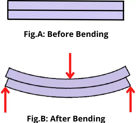
As shown in figure A, consider a simply supported beam consisting of a number of layers.
As shown in figure B, if these layers are free to move over each other, then due to the application of bending load, the adjacent layers will move over each other.
This type of deformation is known as Transverse shear.
But in the actual situation, all the layers are bonded together and each layer tries to resist the slipping of its adjacent layer. Thus the object develops a resistance to avoid the transverse shear.
Therefore the transverse shear stress is the resistance developed by the object to resist the shearing (or splitting) of layers of an object due to bending.
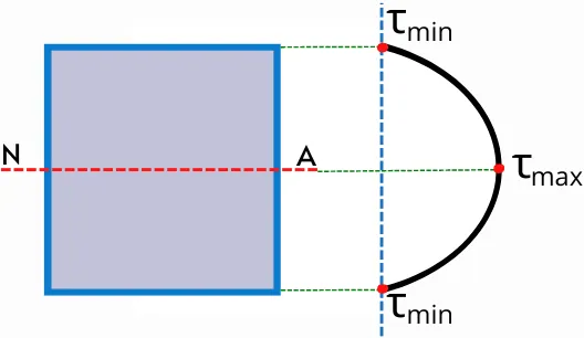
The above figure shows an example of the distribution of transverse shear stress along the cross-section of an object. The value of transverse shear stress is minimum at the extreme fibers (Outermost fiber).
Transverse shear stress formula:
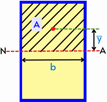
The transverse shear stress at any layer of the cross-section (line xy in figure) can be given by,
`\tau = \frac{FA\bar{y}}{Ib}`
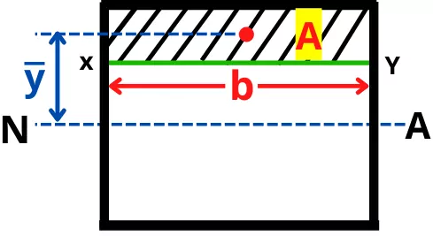
Where,
F = Shear force
Aȳ = Moment of area of the area above XY line about Neutral axis
b = Width of the layer where shear stress has to find
I = Moment of inertia about the neutral axis
The formula can be also written as,
`\tau = \frac{FQ}{Ib}` ——[∵ Q = A`\bar{y}`]
Derivation:
The below figure shows the simply supported beam subjected to the UDL (uniformly distributed load) and its bending moment diagram.
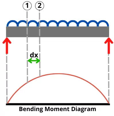
As shown in the figure, consider a smaller section of the beam 1-2 of length dx.
As shown in the bending moment diagram, over the length ‘dx’, the bending moment is increasing by a smaller extent dM.
Thus the bending moment acting on each section of a small element can be drawn as follows,
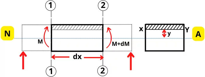
Consider an elemental cross-sectional area dA at a distance y from the neutral axis.
For the above figure, the bending stress acting on elemental cross-sectional area at a distance y from the neutral axis can be given by,
At section 1:-
`\sigma_{1} = \frac{My}{I}`
As section 2:-
`\sigma_{2} = \frac{(M+dM)y}{I}`
Where I = Moment of inertia about Neutral axis.
Due to the bending stress, a force acting on the area dA at sections 1 and 2 can be given by,
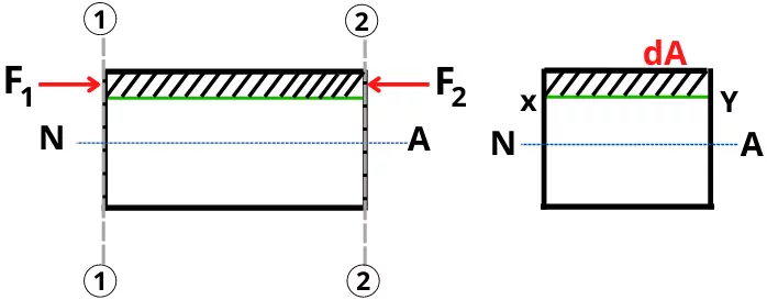
At section 1,
`F_{1} = \sigma_{1} \times dA = \frac{My}{I}.dA`
At section 2,
`F_{2} = \sigma_{2} \times dA = \frac{(M+dM)y}{I}`.dA
From the above equations, it can be concluded that, F2 > F1
This difference between forces F1 and F2 acts as shear force acting on the elemental area dA.
∴ Net shear force acting on portion dA is given by,
`dF_{\text{T. shear}} = F_{2}-F_{1}`
`dF_{\text{T. shear}} = [\frac{(M+dM)y}{I}.dA] – [\frac{My}{I}.dA]`
`dF_{\text{T. shear}} = \frac{dMy}{I}`.dA
Total shear force is given by,
`F_{\text{T. shear}} = \int \frac{dMy}{I}`.dA
`F_{\text{T. shear}} = \frac{dM}{I} \int`y.dA
As ∫y.dA = Q = Moment of area of section above line XY. Thus the equation will become,
`F_{\text{T. shear}} = \frac{dMQ}{I}`
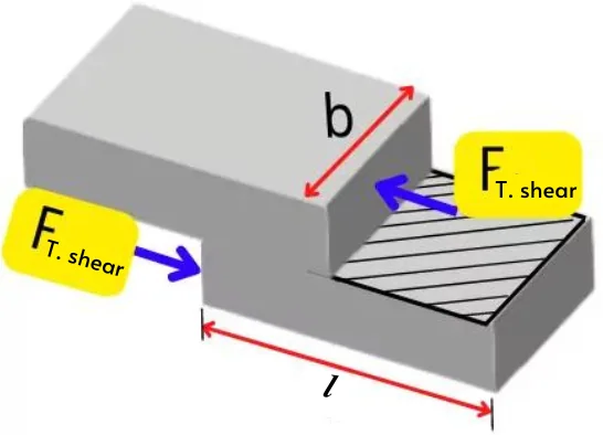
The resisting area for the transverse shear force is given by,
`A_{\text{T. shear}} = l \times b`
Thus the shear stress developed in the object due to the shear force is given by,
`\tau = \frac{F_{\text{T. shear}}}{A_{\text{T. shear}}}`
`\tau = \frac{\frac{dM.Q}{I}}{l.b}`
`\tau = \frac{dM}{l}.\frac{Q}{Ib}`
As `\frac{dM}{l}` = `(\frac{\text{Moment}}{\text{distance}})` = F = shear force, thus the equation will become,
`\mathbf{\tau} = \mathbf{\frac{F.Q}{Ib}}`
This is the equation of transverse shear stress at a distance y from the neutral axis.
As Q = A x y, the equation can also be written as,
`\mathbf{\tau} = \mathbf{\frac{FA.y}{Ib}}`
Formulae for simple geometrical shapes:
Here we have derived equations for the transverse shear stress for some simple shapes.
1] For rectangular cross-section:
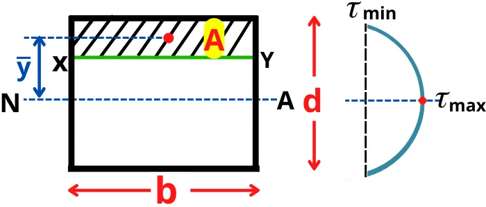
For above cross-section, the transverse shear stress at layer xy can be given by,
`\tau_{xy} = \frac{FA.\bar{y}}{Ib}`
Where,
A = Area above layer XY
ȳ = Position of the centroid of the shaded area (A) from neutral axis
I = Moment of inertia of rectangle about neutral axis = `\frac{bd^{3}}{12}`
Thus the `\tau_{xy}` becomes,
`\tau_{xy} = \frac{12F(A\bar{y})}{b^{2}d^{3}}`
Maximum transverse shear stress:
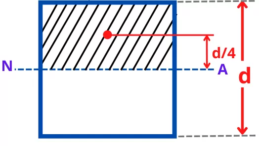
For a rectangle, the maximum transverse shear stress is developed at the neutral axis,
The area above the neutral axis is given by,
A = `b\times \frac{d}{2} = \frac{bd}{2}`
The distance between the centroid of the shaded area from the neutral axis is given by,
`\bar{y} = \frac{d}{4}`
Thus by putting these values, the equation for maximum transverse shear stress becomes,
`\tau_{xy} = \frac{3F}{2bd}`
2] For circular section:-
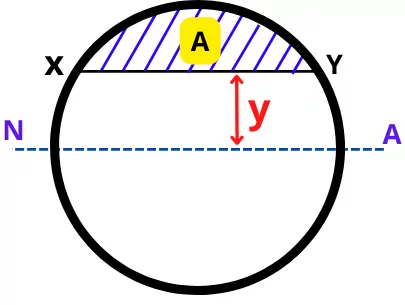
For the circular section, the moment of area (Aȳ) for the area above line XY can be calculated as,
Aȳ = `\frac{2}{3} (R^{2} – y^{2})^\frac{3}{2}`
Where,
y = Distance of layer from Neutral axis
R = Radius of circle
Thus by putting Aȳ in the below equation, we can find the transverse shear stress at line XY.
`\tau_{xy} = \frac{FA\bar{y}}{Ib}`
Maximum transverse shear stress:-
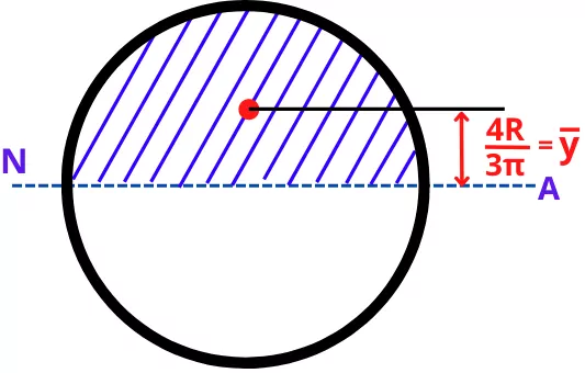
The maximum transverse shear stress is observed at the neutral axis.
The area above the neutral axis is given by,
A = `\frac{\pi R^{2}}{2}`
The distance between the centroid of the shaded area from the neutral axis is given by,
ȳ = `\frac{4R}{3\pi}`
The moment of inertia about the neutral axis is given by,
I = `\frac{\pi}{4}R^{4}`
And the width at the neutral axis is given by,
b = 2R
Thus the maximum value of transverse shear stress at the Neutral axis is given by,
`\tau_{\text{max}} = \frac{FA\bar{y}}{Ib}`
`\tau_{\text{max}} = \frac{F(\frac{\pi R^{2}}{2}).(\frac{4R}{3\pi})}{(\frac{\pi}{4}R^{4})\times (2R)}`
`\tau_{\text{max}} = \frac{4F}{3\pi R^{2}}`
How to find Transverse shear stress?
The transverse shear stress at any location of the beam can be found by using the following steps:-
Step 1] Find the amount of shear force (F) acting on beam at the location.
Step 2] Find the position of the neutral axis for the cross-section.
Step 3] Find the moment of inertia about the neutral axis (`I_{NA}`).
Step 4] Find first moment of area of the area above the line about the neutral axis (Aȳ)
Step 5] Find the width of a cross-section at a location where shear stress has to be found (b).
Step 6] Find transverse shear stress by using the below formula.
`\tau = \frac{FA.\bar{y}}{I_{NA}b}`
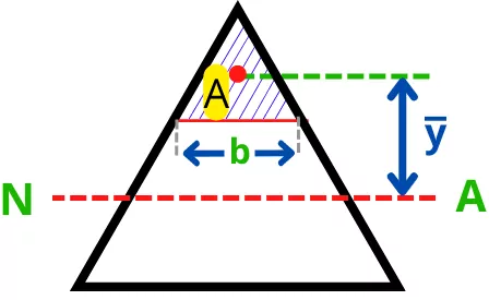
How to calculate maximum transverse shear stress?
The maximum transverse shear stress mostly acts at the position of the neutral axis. The consideration becomes wrong for the beam with a triangular cross-section.
Except for cross-sections with triangles, use the following steps to find the maximum transverse shear stress on the beam with a homogeneous cross-section.
Step 1] Find the maximum shear force (F) acting on the beam.
Step 2] Find the position of the neutral axis of the beam.
Step 3] Find the first moment of area (Aȳ) of the area above the neutral axis about the neutral axis.
Step 4] Find the moment of inertia of the cross-section about the Neutral axis (`I_{NA}`).
Step 5] Find the width of the cross-section at the neutral axis.
Step 6] Find maximum shear stress by using the below formula,
`\tau_{\text{max}} = \frac{FA.\bar{y}}{I_{NA}b}`
Note:
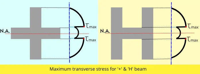
In the case of the beam with a ‘+’ or ‘H’ shape cross-section, if the neutral axis lies at the portion of higher width, then we need to compare the transverse shear stress at the following two locations for getting the maximum value.
a] At neutral axis
b] location near the neutral axis where the width of the beam decreases.
Below is an example of shear stress distribution for a beam with a ‘+’ or ‘H’ shape cross-section.
Transverse shear stress vs shear stress:
| Sr. No. | Transverse shear stress | Shear stress |
|---|---|---|
| 1 | It results due to the bending load. | It arises due to the direct load. |
| 2 | The force is perpendicular to the shear area. | The force is parallel to the shear area. |
| 3 | The stress value varies across the cross-section. | The stress value is the same across the cross-section. |
Transverse shear stress examples:
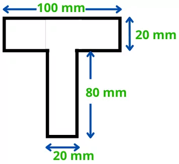
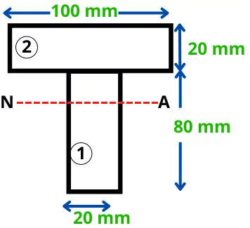
| The beam with a T-section is subjected to the maximum shear force of 6 KN. Find the maximum transverse shear stress acting on the beam. |
Solution:-
Step 1] Maximum shear force:
F = 6 KN = 6000 N
Step 2] Position of neutral axis:-
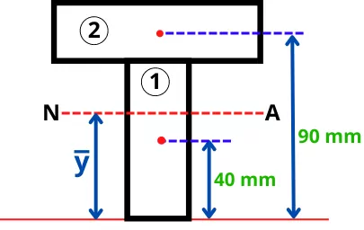
Divide the cross-section in simple shapes.
The area of each shape is given by,
A1 = 80 x 20 = 1600 mm²
A2 = 100 x 20 = 2000 mm²
Position of centroid of each shape is given by,
`y_{1} = \frac{80}{2}` = 40 mm
`y_{2} = 80 + \frac{20}{2}` = 90 mm
Position of the neutral axis from bottom is given by,
`\bar{y} = \frac{A_{1}y_{1}+A_{2}y_{2}}{A_{1}+A_{2}}`
`\bar{y} = \frac{1600\times 40+2000\times 90}{1600+2000}`
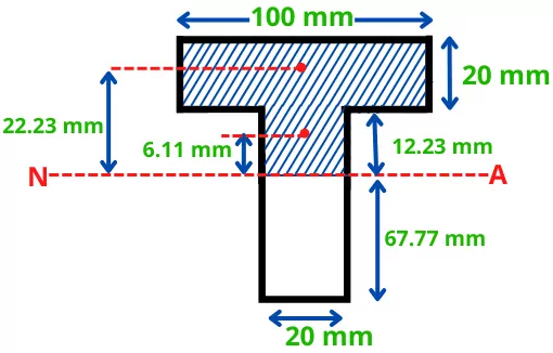
ȳ = 67.77 mm
Step 3] First moment of area about neutral axis of the area above neutral axis:
The moment of area about neutral axis is given by,
Q = Aȳ = [(20 x 12.23) x 6.11] + [(100 x 20) x 22.23]
Aȳ = 45954.506 mm³
Step 4] Moment of inertia about neutral axis `(I_{NA})`:
Moment of inertia of section 1 about a neutral axis is given by,
`I_{1NA} = I_{1} + A_{1}(y_{1}-\bar{y})^{2}`
`I_{1NA} = \frac{20\times 80^{3}}{12} + 1600(40-67.77)^{2}`
`\mathbf{I_{1NA}}` = 2087210 mm⁴
Moment of inertia of section 2 about a neutral axis is given by,
`I_{2NA} = I_{2} + A_{2}(y_{2}-\bar{y})^{2}`
`I_{2NA} = \frac{100\times 20^{3}}{12} + 2000(90-67.77)^{2}`
`\mathbf{I_{2NA}}` = 1055012.46 mm⁴
Total moment of inertia about a neutral axis is given by,
`I_{NA} = I_{1NA}+I_{2NA}`
`I_{NA}` = 2087210 + 1055012.46
`\mathbf{I_{NA}}` = 3142222.46 mm⁴
Step 5] Width at the neutral axis,
b = 20 mm
Step 6] Maximum transverse shear stress,
`\tau_{\text{max}} = \frac{FA\bar{y}}{I_{NA}b}`
`\tau_{\text{max}} = \frac{6000\times 45954.506}{3142222.46\times 20}`
`\mathbf{\tau_{\text{max}}}` = 4.38 N/mm2
This is the maximum value of shear stress into the beam.
FAQs:
-
Why transverse shear stresses are generated?
Transverse shear stress causes because of the bending load acting on the object.
-
Where is the maximum transverse shear stress found?
For most of the cross-sections, the maximum transverse shear stress acts at the neutral axis. (except triangular cross-section, it has a maximum value at mid of height).
-
How transverse shear stress differs from shear stress?
In transverse shear stress, the deformation occurs perpendicular to the direction of the applied force while in shear stress, the deformation occurs parallel to the direction of the applied force.