The angle of twist indicates the degree of twisting (angular deformation) in object subjected to couple of torque or twisting load. The parameter is crucial in the design of torsion-resistant mechanical components.
Contents:
What is the Angle of twist?
Angle of twist equation:
Factors affecting Angle of twist:
How is the Angle of twist calculated?
Angle of twist for different cross-sections:
Angle of twist Vs Angle of shear- Difference:
Angle of twist examples:
FAQs:
What is the Angle of twist?
The angle of twist is the measure of angular deformation formed in an object by a couple of twisting torques. The twisting torque cause torsional shear, which results in the twisting of an object.
The angle of twist gives the rotation angle turned by planes of application of twisting torque. The term angle of twist is denoted by the symbol ‘θ’ and it is expressed by the unit of degree or radian.

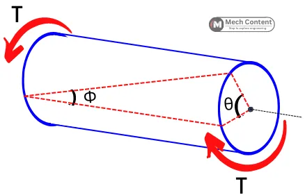
The above figure shows the torque applied along the longitudinal axis of the shaft, this twisting torque causes the material of the object to deform in an angular manner.
Here the angle ‘Φ’ measured over the cylindrical surface indicates the angle of shear or shear strain and the angle ‘θ’ indicates the angle of twist in the object.
Let me make things easier for you.
Let’s consider the shaft made by a number of thin discs, placing one over another.
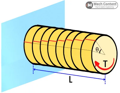
When the twisting torque is applied, each disc will rotate over its adjacent disc (due to the torsional shear).
Here the degree of rotation of the last disc with respect to the first disc indicates the angle of twist (θ) in the ‘L’ length of the shaft.
From the torsional equation, the angle of twist is given by,
`\theta = \frac{TL}{GJ}`
Where,
T = Twisting torque
L = Length over which torque is applied
J = Polar moment of inertia about a torsional axis
G = Shear modulus
From the above equation, it is clear that the angle of twist is directly proportional to the applied torque (T) and the length of the shaft (L) and inversely proportional to the shear modulus (G) and polar moment of inertia (J) of the cross-section.
Generally, the shafts and axles are designed in such a way that it has a minimum angle of twist.
Angle of twist equation:
a] Shaft with same cross-section and internal torque:
For the shaft with a length of L, Modulus of rigidity G, and Polar moment of inertia of J, the angle of twist is given by,
`\theta =\frac{T L}{GJ}`
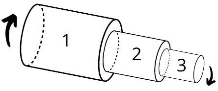
b] Shaft with changing cross-section and internal torque:
For the shaft with different cross-section steps and with n number of twisting torque, the angle of twist is given by,
`\theta = \theta_{1} + \theta_{2}+\cdots+\theta_{n}`
`\theta = \frac{T_{1}L_{1}}{G_{1}J_{1}}+\frac{T_{2}L_{2}}{G_{2}J_{2}}+\cdots \frac{T_{n}L_{n}}{G_{n}J_{n}}`
`\theta = \sum_{i=1}^{n}\frac{T_{i}L_{i}}{G_{i}J_{i}}`
Where,
Ti = internal torque on each section
Li = Length of each section
Gi = Shear modulus of each section
Ji = Polar moment of inertia for each section
c] Shaft with varying cross-section:
For the shaft with a varying cross-section, the angle of twist is given by,
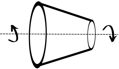
`\theta = \int_{0}^{L}\frac{Tdx}{GJ}`
Factors affecting Angle of twist:
The angle of twist in an object subjected to the torsional load depends on the following factors:
- Internal torque: Higher the torque, the angle of twist in the object will be higher.
- Length of shaft: The twist angle increases with an increase in the length of the shaft. Hence longer shafts show higher twisting than shorter shafts.
- Material property: The twisting angle is inversely proportional to the shear modulus of the shaft. It means that the shafts with a higher value of G show less twisting.
- Geometry of the cross-section: The twist angle decreases with an increase in the polar moment of inertia of the cross-section about a torsional axis. Therefore shafts with a higher value of ‘J’ has a lesser angle of twist.
How is the Angle of twist calculated?
Here are the steps to calculate the angle of twist (θ) in a shaft.
1] Divide the shaft into a number of sections (if necessary):
If the object is experiencing multiple torques, then divide the shaft into sections, in such a way that each section will experience constant internal torque.
If the object has different steps of cross-section, then also divide the shaft into a number of sections with each section having the same cross-section.
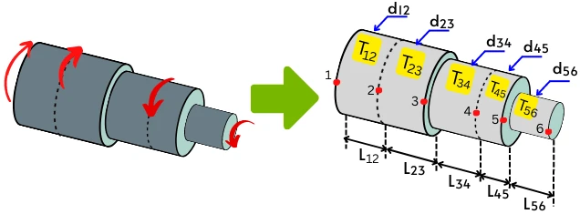
2] Find internal torque in each section. (T12, T23, T34, etc.)
3] Find the Polar moment of inertia (J) for the cross-section of each section. (J12, J23, J34, etc.)
4] Find the length of each section of the shaft. (L12, L23, L34, etc.)
5] Find the Shear modulus (G) of each section. (G12, G23, G34, etc.)
6] Find the angle of twist of each section separately and then add them all together to get the total angle of twist in a shaft. Or use the below formula.
`\theta = \frac{T_{12}L_{12}}{G_{12}J_{12}}+\frac{T_{23}L_{23}}{G_{23}J_{23}}+\cdots \frac{T_{n}L_{n}}{G_{n}J_{n}}`
See the below numerical to know how to use the above steps to find the θ.
Angle of twist for different cross-sections:
Following are the angle of twist for the shaft’s different cross sections.
1] Circular shaft:
a] The J for the solid circular shaft of diameter ‘d’ is given by,
`J = \frac{\pi}{32}.d^{4}`
Thus the angle of twist for the solid circular shaft is given by,
`\theta = \frac{TL}{GJ} = \frac{TL}{G}.\frac{32}{\pi.d^{4}}`
`\theta = \frac{32TL}{\pi.G.d^{4}}`
b] The J for the hollow circular shaft of outer diameter ‘do‘ and inner diameter ‘di‘ is given by,
`J = \frac{\pi}{32}.[d_{o}^{4} – d_{i}^{4}]`
The angle of twist for the hollow circular shaft is given by,
`\theta = \frac{TL}{GJ} = \frac{TL}{G}.\frac{32}{\pi[d_{o}^{4} – d_{i}^{4}]}`
`\theta = \frac{32TL}{\pi.G. [d_{o}^{4} – d_{i}^{4}]}`
2] Rectangular cross-section shaft:
The polar moment of inertia for the rectangular cross-section (b×d) is given by,
`J = \frac{b.d^{3}+d.b^{3}}{12}`
The θ is given by,
`\theta = \frac{TL}{GJ} = \frac{TL}{G}.\frac{12}{ b.d^{3}+d.b^{3}}`
`\theta = \frac{12TL}{G.[ b.d^{3}+d.b^{3}]}`
Angle of twist Vs Angle of shear- Difference:
The below figure will help you to understand the difference between the angle of twist and the angle of shear.
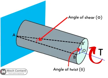
Line AB in the figure is the initial reference line drawn onto the surface of the cylinder before twisting that is parallel to the axis of the cylinder. Here one end of the cylinder is fixed and another end is subjected to the torque T.
After the application of torque, the cylinder gets twisted and point B shifts to the new position B’.
The angle of shear is the angle made by the reference line with its initial position i.e. ∠BAB’ = Φ. While the angle made by the line OB with its initial position is the angle of twist i.e. ∠BOB’ = θ.
The Angle of shear never depends on the length of the shaft. It remains the same for any length of the shaft. While the angle of twist is different at different lengths of shafts.
The angle of shear is measured on the surface of an object while the angle of twist is measured over the cross-section of an object.
Angle of twist examples:
1) The aluminum shaft of length 1 m, G = 24 GPa, and having a diameter of 40 mm is twisted by the torque of 100 N.m. Find the twist angle (θ) in the shaft.
Given:
G = 24 GPa= 24 × 10³ N/mm²
d = 40 mm
T = 100 N.m = 100 × 10³ N.mm
L = 1 m = 1000 mm
Solution:
Step 1] Polar moment of inertia:
For circle,
`J=(\frac{\pi }{32})d^{4}=(\frac{\pi }{32})40^{4}`
J = 251327 mm4
Step 2] Angle of twist:
The θ in the shaft is given by,
`\theta = \frac{TL}{JG}`
`\theta = \frac{(100\times 10^{3})\times 1000}{251327\times (24\times 10^{3})}`
θ = 0.016 radian
2) For the aluminum shaft, the limiting value of θ is 0.1 radian. If the shaft has a length of 1m with a diameter of 50, calculate a minimum permissible value for torque. (Assume, G = 25 GPa).
Given:
L = 1 m = 1000 mm
θ = 0.1 radian
d = 50 mm
G = 25 GPa = 25 × 10³ N/mm²
Solution:
Step 1] Polar moment of inertia:
For circle,
J =`\frac{\pi }{32}d^{4}`
J =`\frac{\pi }{32}\times 50^{4}`
J = 613592 mm4
Step 2] Maximum torque (T):
`\theta = \frac{TL}{JG}`
`0.1=\frac{T\times 1000}{613592\times (25\times 10^{5})}`
T = 1533980 N.mm
FAQs:
-
How angle of twist depends on the torque?
The relation is given by,
Angle of twist = [Lenght/(Shear modulus × Polar moment of inertia)] × Torque -
How geometry of the object affects the angle of twist?
The angle of twist decreases with an increase in the polar moment of inertia and decreases with an increase in the longitudinal length of the object.
Read also: