Polar moment of inertia vs moment of inertia can differentiate as the polar moment of inertia shows the resistance offered by an object to deformation by torsional load and the moment of inertia shows the resistance offered by a cross-section of the object to the deformation (caused by bending load).
In this article, we’re going to discuss:
- Polar moment of inertia:
- Moment of inertia:
- Difference between moment of inertia and polar moment of inertia:
- FAQ’s
Polar moment of inertia:
The Polar moment of inertia is associated with the cross-section of an object that shows the resistance offered by an object to deformation caused by torsional loading.
It is one of the types of the second moment of area that is generally denoted by the symbol ‘J’.
The SI unit of the polar moment of inertia is m⁴ and the FPS unit is Ft⁴.
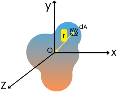
From the above diagram, the Polar moment of inertia about the z-axis is given by,
`J_{Z}` = `\int` r².dA
Moment of inertia:
The moment of inertia shows the distribution of cross-sectional area from a specific reference axis. It is also known as the planar moment of inertia and it is one of the types of the second moment of area.
The moment of inertia represents the amount of resistance offered by the cross-section to the deflection due to the bending loads.
It is generally denoted by the symbol ‘ 𝙸 ‘ and the reference axis for finding a moment of inertia always lies in a planar surface.
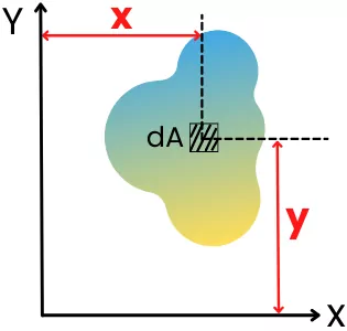
For the cross-section shown in the above figure, the moment of inertia about the x-axis is given by,
`I_{\text{xx}}` = `\int` y².dA
And the moment of inertia of the above cross-section about the y-axis is given by,
`I_{yy}` = `\int` x².dA
Difference between moment of inertia and polar moment of inertia:
| Sr. No. | Polar moment of inertia | Moment of inertia |
|---|---|---|
| 1] | The polar moment of inertia is the resistance offered by the cross-section to torsional load. | The moment of inertia is the resistance offered by the surface to the bending deformation. |
| 2] | The polar moment of inertia is taken about an axis perpendicular to the plane of cross-section passing through the centroid. | The moment of inertia is calculated for the axis lying into the plane of cross-section. |
| 3] | The polar moment of inertia is used to analyze torsional loading in shafts. | The moment of inertia is used for analyzing beams or other flexural members subjected to the bending load. |
| 4] | The polar moment of inertia is denoted by the symbol ‘J’. | The moment of inertia is generally denoted by the symbol ‘𝙸‘. |
| 5] | The torsional stiffness (K) depends on the polar moment of inertia. | The bending stiffness of the member depends on the moment of inertia. |
| 6] | For the same cross-section, the polar moment of inertia is greater than a moment of inertia. | For the same cross-section, the moment of inertia at any axis is smaller than a polar moment of inertia. |
FAQ’s
-
How moment of inertia is related to polar moment of inertia?
The relation between the moment of inertia and the polar moment of inertia can be given by using the perpendicular axis theorem.
J𝗈 = 𝙸𝗑 + 𝙸𝗒
Where,
J𝗈 = Polar moment of inertia
𝙸𝗑 and 𝙸𝗒 = Moment of inertia about mutually perpendicular axes (x and y axis) which are lying in the plane of cross-section. -
What is the relationship between moment of inertia I and polar moment of inertia J for a circular section?
For circular cross-section, the relationship between the moment of inertia and polar moment of inertia is given by,
Polar moment of inertia (J) = 2 x (Moment of inertia about centroid)
As 𝙸 = (π/64)D⁴
∴ J = (π/32)D⁴ = 2 x (π/64)D⁴ = 2 𝙸